
Agricultural unmanned aerial vehicle for agricultural planting

An unmanned aerial vehicle and agricultural technology, which is applied in the field of agricultural unmanned aerial vehicles for agricultural planting, can solve the problems of increasing the burden of unmanned aerial vehicles and shortening the service life of unmanned aerial vehicles, so as to prevent interference, increase the distribution range, and prevent the damage effect

Pending Publication Date: 2020-11-06
张红新
View PDF11 Cites 4 Cited by
  • Summary
  • Abstract
  • Description
  • Claims
  • Application Information

AI Technical Summary

Problems solved by technology

An agricultural UAV spraying mechanism in the above-mentioned patent has the following disadvantages: when the existing UAV sprays pesticides, in order to prevent the precipitation of the pesticides from affecting the properties of the pesticides, the pesticides will be stirred. However, the existing UAVs usually use electricity to stir pesticides, which may increase the burden on the UAV and reduce the service life of the UAV

Method used


Image

  • Agricultural unmanned aerial vehicle for agricultural planting
  • Agricultural unmanned aerial vehicle for agricultural planting
  • Agricultural unmanned aerial vehicle for agricultural planting

Examples


Embodiment 1

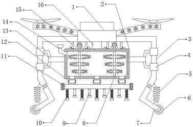
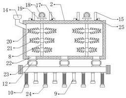
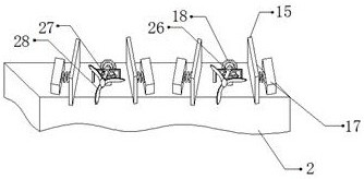
[0030] refer to Figure 1-3 , an agricultural drone for agricultural planting, including a drone body 1, the bottom outer wall of the drone body 1 is connected with a fixed shaft 16 by bolts, and the bottom outer wall of the fixed shaft 16 is connected with a liquid storage tank 2 by bolts, One side outer wall of the liquid storage tank 2 is provided with a liquid inlet, and the inner wall of the liquid inlet is provided with a liquid inlet pipe 14, and the top inner wall of the liquid storage tank 2 is connected with a rotating rod 8 through bearing rotation, and the two rotating rods 8 One side of the outer wall extends to the outside of the liquid storage tank 2, the outer walls of the two rotating rods 8 are connected with the stirring shaft 20 by bolts, and the size of the stirring shaft 20 decreases from top to bottom, and the top outer walls of the two rotating rods 8 are The first bevel gear 18 is connected by bolts, and the both sides of the outer wall of the top of t...

Embodiment 2

[0041] refer to Figure 4 , an agricultural unmanned aerial vehicle for agricultural planting. Compared with Embodiment 1, this embodiment has sockets on both sides of the top outer wall of the liquid storage tank 2, and a liquid level gauge 29 is inserted into the inner walls of the two sockets, which can The liquid level inside the liquid storage tank 2 is detected. When the pesticide spraying in the liquid storage tank 2 is finished, the liquid level gauge 29 will transmit the signal to the people on the ground, so as to facilitate the recovery of the drone body 1 .

[0042] Working principle: when in use, when the pesticide needs to be sprayed, the pesticide is filled into the liquid storage tank 2 through the liquid inlet pipe 14, and the drone body 1 is started, and the drone body 1 will drive the liquid storage tank 2 to fly. Thereby, the crops are sprayed, and the drone body 1 will generate wind force when flying, and the blades 28 will be driven to rotate due to the w...


PUM


Abstract

The invention discloses an agricultural unmanned aerial vehicle for agricultural planting, which comprises an unmanned aerial vehicle body, wherein the outer wall of the bottom of the unmanned aerialvehicle body is fixedly connected with a fixed shaft; a liquid storage tank is fixedly connected to the outer wall of the bottom of the fixed shaft; a liquid inlet is formed in the outer wall of one side of the liquid storage tank; a liquid inlet pipe is arranged on the inner wall of the liquid inlet; rotating rods are rotatably connected to the inner wall of the top of the liquid storage tank through bearings; the outer walls of one sides of the two rotating rods extend to the exterior of the liquid storage tank; stirring shafts are fixedly connected to the outer walls of the two rotating rods; the sizes of the stirring shafts are sequentially reduced from top to bottom; and first bevel gears are fixedly connected to the outer walls of the top of the two rotating rods. According to the agricultural unmanned aerial vehicle, pesticide precipitation can be prevented from influencing pesticide properties of pesticides, birds can be prevented from interfering with pesticide spraying, the wind strength can be improved, damage to the stirring shaft due to large hydraulic pressure can be prevented, the pesticides can be conveniently subjected to impurity removal treatment, and the workingefficiency of the unmanned aerial vehicle can be improved.

Description

technical field [0001] The invention relates to the technical field of agricultural planting, in particular to an agricultural drone for agricultural planting. Background technique [0002] Due to the continuous development of large-scale planting, the demand for large-scale spraying equipment is also increasing, and drones can spray pesticides and fertilizers on crops. Used in agriculture. [0003] After retrieval, the Chinese patent authorization number is CN209600813U, which discloses an agricultural drone spraying mechanism, including a drone mechanism, a connecting mechanism, a drug dispensing mechanism and a spraying mechanism. The connecting mechanism is fixedly installed at the bottom of the drone mechanism At the center, the spraying mechanism is movably installed at the bottom of the connecting mechanism, and the drug dispensing mechanism is fixedly installed on the top outer surface of the spraying mechanism. The drone mechanism includes a drone frame, and the ou...

Claims


Application Information

Patent Timeline
IPC IPC(8): B64D1/18A01M7/00B01F7/16B01F15/00B01F13/00
CPCB64D1/18A01M7/0025B01F27/2322B01F27/191B01F27/85B01F33/5021B01F35/32065B01F2101/04
Inventor 张红新
Owner 张红新
Learn More