Unmanned aerial vehicle topographic survey device

A technology for terrain surveying and unmanned aerial vehicles, which is applied to surveying devices, aircraft indicating devices, unmanned aerial vehicles, etc., can solve the problems of inability to shrink and hide, block the view of the lens, and poor practicability, and achieve streamlined cleaning steps and operations. Flexible, convenient, efficient, and precise pop-up protection

Inactive Publication Date: 2020-11-06
嘉兴勤慎智能技术有限公司
View PDF10 Cites 3 Cited by
  • Summary
  • Abstract
  • Description
  • Claims
  • Application Information

AI Technical Summary

Problems solved by technology

[0005] The purpose of the present invention is to provide a UAV topographic measurement device to solve the problem that most of the lens protection components of the UAV measurement device proposed in the background technology are integrated with crosspieces and installed directly below the lens, which cannot be flexibly shrunk and hidden. Does not have the function of active defense and automatic pop-up, which will block the view of the lens, and the problem of poor practicability

Method used


Image

  • Unmanned aerial vehicle topographic survey device
  • Unmanned aerial vehicle topographic survey device
  • Unmanned aerial vehicle topographic survey device

Examples


Embodiment Construction

[0032] The following will clearly and completely describe the technical solutions in the embodiments of the present invention with reference to the accompanying drawings in the embodiments of the present invention. Obviously, the described embodiments are only some, not all, embodiments of the present invention.

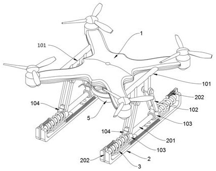
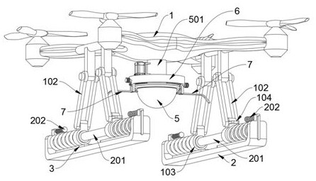
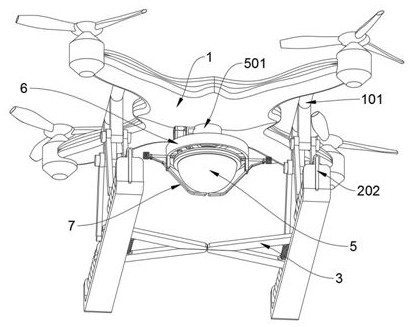
[0033] see Figure 1 to Figure 11, an embodiment provided by the present invention: an unmanned aerial vehicle topographic measuring device, including a body 1, a base plate 2, a motor 4 and a measuring lens 5, and the body 1 includes a supporting shaft 101, a connecting rod 102, and a slip ring 103 and top stamping plate 104, there are four cantilevers on the left side of the body 1, and there are two supporting shafts 101 symmetrically supported between them. The bottoms of the two supporting shafts 101 are suspended and connected to two connecting rods 102, and The tail ends of the four connecting rods 102 are all rotatably connected with a slip ring 103; the top ...


PUM


Abstract

The invention discloses an unmanned aerial vehicle topographic survey device, relates to the technical field of unmanned aerial vehicles, and solves the problems that most of lens protection assemblies of existing unmanned aerial vehicle survey devices are integrated and transversely mounted under lenses in a blocking manner, cannot be flexibly contracted and hidden, do not have an active defenseautomatic pop-up function, can block the vision field of the lenses and are poor in practicability. The unmanned aerial vehicle topographic survey device comprises a machine body, base plates, a motorand a measuring device, wherein two supporting connecting shafts are symmetrically supported between four cantilevers on the left and right of the machine body, two connecting rods are connected to the lower portions of the bottom of the two supporting connecting shafts in a hanging and rotating mode, and the tail ends of the four connecting rods are each connected with a slip ring in a rotatingmode; and four top poking plates are welded on convex blocks at the top ends of the four slip rings in a front-back opposite supporting manner. According to the invention, the four barrier plates canbe horizontally positioned and hidden at the top ends of the two base plates when not in use, so that shooting and measuring obstacles caused by the fact that the four barrier plates are normally opened and transversely blocked at the bottom of the measuring device are avoided.

Description

technical field [0001] The invention relates to the technical field of unmanned aerial vehicles, in particular to an unmanned aerial vehicle terrain measurement device. Background technique [0002] UAV is an unmanned aircraft operated by radio remote control equipment and self-contained program control device, or completely or intermittently operated autonomously by on-board computer. UAV can be divided into military and civilian, military In terms of drones, they are divided into reconnaissance drones and target drones. In terms of civilian use, the application of UAV industry is the real rigid demand of UAV. At present, it is used in aerial photography, agriculture, plant protection, micro selfie, express delivery, disaster rescue, observation of wild animals, monitoring of infectious diseases, surveying and mapping, news reports, power inspection Applications in fields such as disaster relief, film and television shooting, and romance manufacturing have greatly expanded...

Claims


Application Information

Patent Timeline
Patent Type & Authority Applications(China)
IPC IPC(8): B64D47/08B64D45/00B64C27/08G01C7/04
CPCB64D47/08B64D45/00B64C27/08G01C7/04B64U2101/30B64U10/10
Inventor 牛庾鑫
Owner 嘉兴勤慎智能技术有限公司
Why Eureka
Try Eureka