
A palletizing conveyor belt for sludge brick production

A technology for making bricks and conveyor belts from sludge, which is applied in the production of conveyors, conveyor objects, ceramic materials, etc. It can solve the problems of inability to layer and achieve the effect of simple structure and conducive to stacking and stacking operations

Active Publication Date: 2022-01-14
合肥佳安建材有限公司
View PDF10 Cites 0 Cited by
  • Summary
  • Abstract
  • Description
  • Claims
  • Application Information

AI Technical Summary

Problems solved by technology

[0004] What the present invention aims to overcome is that the traditional conveyor belt adopts a tiled type, and the problem of layering cannot be carried out during the brick material conveying process, and the purpose is to provide a palletizing conveyor belt for sludge brick production

Method used


Image

  • A palletizing conveyor belt for sludge brick production
  • A palletizing conveyor belt for sludge brick production

Examples


Embodiment 1

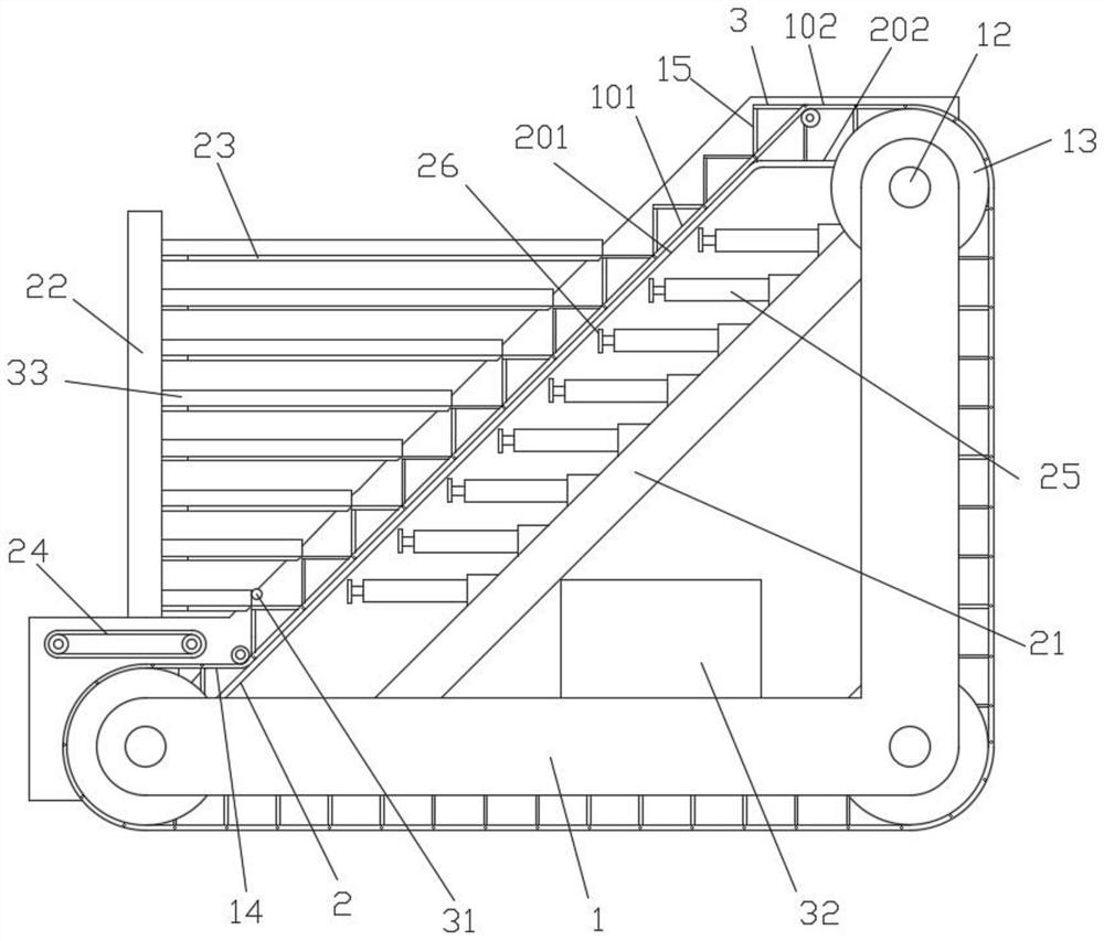
[0022] Such as figure 1 , figure 2 Shown; A kind of sludge brick production palletizing conveyor belt, comprising:

[0023] Device support 1, a plurality of drive rollers 12 are installed on the device support 1, the drive rollers 12 are driven by a drive motor, each drive roller 12 two ends are respectively equipped with a drive chain disc 13, and a drive belt chain 14 is installed on the drive chain disc 13;

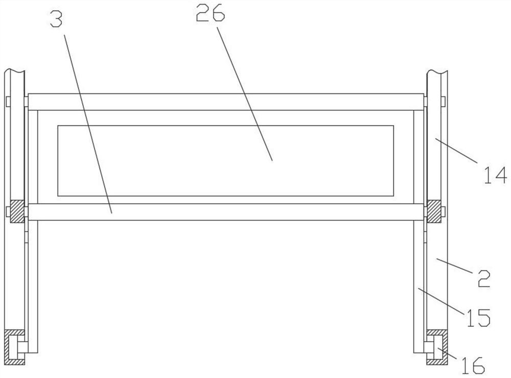
[0024] Guide slideway 2, guide slideway 2 is provided with two, is respectively fixedly installed on the device support 1 of drive roller 12 two ends, and guide slideway 2 is positioned at driving belt chain 14 inner side;

[0025] Support plate 3, support plate 3 is provided with a plurality of, equidistantly hinged on the drive belt chain 14, support plate 3 is away from drive belt chain 14 hinged side and is vertically fixedly installed with two struts 15, each strut 15 lower ends are respectively A roller 16 is installed, and the roller 16 is located inside the ...

Embodiment 2

[0030] On the basis of Example 1, such as figure 1 Shown; The horizontal distance between the tail end of the material receiving plate 23 and the chain a section 101 is equal to the width of the supporting plate 3 . It is ensured that the support plate 3 can be smoothly pushed out onto the receiving plate 23 .

[0031] An infrared sensor 31 is fixed at the end of the bottommost material receiving plate 23 on the material receiving column 22 , the infrared sensor 31 is connected to the input end of the controller 32 , and the output end of the controller 32 is respectively connected to the driving motor and the electric push rod 25 . Utilize the infrared sensor 31 to detect whether there is a brick on the support plate 3 moved to the horizontal position of the bottom receiving plate 23. When there is a brick, the infrared sensor 31 feeds back a signal to the controller 32, and the controller 32 controls the drive motor to stop working. The drive belt chain 14 stops moving, and...


PUM


Abstract

A palletizing conveyor belt for sludge brick production, comprising: a device bracket, a guide slideway, a support plate, a plurality of driving rollers are installed on the device bracket, the driving rollers are driven by a driving motor, and two ends of each driving roller are respectively installed The drive chain plate is equipped with a drive belt chain; there are two guide slides, which are respectively fixed on the device brackets at both ends of the drive roller, and the guide slides are located inside the drive belt chain; there are multiple support plates, Hinged on the drive belt chain at equal intervals, two support rods are fixed vertically on the side away from the hinge of the drive belt chain, and the lower end of each support rod is respectively equipped with rollers, and the rollers are located inside the guide slideway; use the electric push rod to push the push rod The plate moves, and the push plate passes through the two support rods to push the rows of bricks on the support plate into the material receiving plate. During the whole conveying process, the bricks can be layered into the material receiving plate, which is beneficial to the subsequent stacking stack operation.

Description

technical field [0001] The invention relates to the field of sludge brick production equipment, in particular to a palletizing conveyor belt for sludge brick production. Background technique [0002] Sludge contains a large amount of organic matter and rich nitrogen, phosphorus and other nutrients. Arbitrary discharge into the water body will consume a large amount of oxygen in the water body, resulting in deterioration of the water quality and seriously affecting the survival of aquatic organisms. In addition, there are a variety of toxic substances, heavy metals, pathogenic bacteria, parasite eggs and other harmful substances in the sludge. Improper treatment will spread diseases, pollute the soil and crops, and pass them on to humans through the biological chain. Therefore, if the sludge is discharged and stacked arbitrarily without proper treatment, it will definitely cause serious pollution to the surrounding environment, so that the established sewage plants cannot ful...

Claims


Application Information

Patent Timeline
Patent Type & Authority Patents(China)
IPC IPC(8): B65G17/16B65G17/34B65G17/38B65G17/48B65G43/08B65G47/22B65G47/57B65G47/82B65G57/11C04B33/132
CPCB65G17/16B65G17/34B65G17/38B65G17/48B65G47/82B65G43/08B65G47/57B65G47/22B65G57/11C04B33/1321Y02P40/60
Inventor 李俊李超石雅军胡惠明叶斌斌周守仓朱焕胜
Owner 合肥佳安建材有限公司
Learn More