Quantitative traceless cutting equipment for glass

A quantitative traceless and cutting equipment technology, applied in glass manufacturing equipment, glass cutting devices, manufacturing tools, etc., can solve the problems of error, small size, and low cost

Inactive Publication Date: 2020-11-06
刘洋
View PDF7 Cites 8 Cited by
  • Summary
  • Abstract
  • Description
  • Claims
  • Application Information

AI Technical Summary

Problems solved by technology

[0002] At present, glass cutting can be divided into automatic glass cutting machine and manual portable glass cutting machine in terms of power. Automatic glass cutting machine is generally used in glass production and processing. It has good processing quality, fast efficiency and high machine cost. ;The most common type of manual portable glass cutting machine is a glass cutter, which is small in size and low in cost, and is suitable for various processing environments. It is difficult to accurately locate the length of glass cutting in conventional methods, and the cutting accuracy is low. It is cut by a cutting machine. The cutting knife set by the cutting machine is easy to shake when rotating, and it is inevitable to cause errors during cutting, damage the glass, and lead to waste of products. Therefore, we propose a method for glass quantification. scar cutting equipment in order to solve the problems raised above

Method used


Image

  • Quantitative traceless cutting equipment for glass
  • Quantitative traceless cutting equipment for glass
  • Quantitative traceless cutting equipment for glass

Examples


Embodiment Construction

[0031] The following description serves to disclose the present invention to enable those skilled in the art to carry out the present invention. The preferred embodiments described below are only examples, and those skilled in the art can devise other obvious variations.

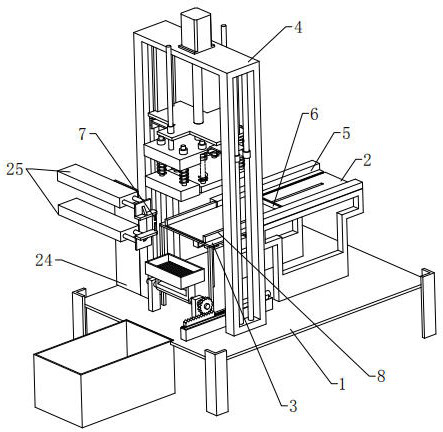
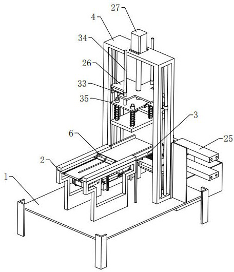
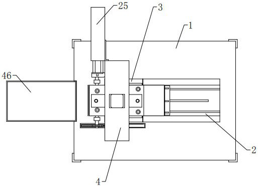
[0032] refer to Figure 1 to Figure 13 As shown, a quantitative non-mark cutting equipment for glass, including a processing table 1, a conveying table 2, a cutting table 3, a gantry frame 4, a scratching mechanism, a quantitative pushing mechanism, a positioning mechanism, a pressing mechanism and a waste collection Mechanism, the conveying table 2 is set on the top of the processing table 1, the top of the conveying table 2 is provided with a slideway 5 for glass movement, the cutting table 3 is arranged at the end of the conveying table 2, the gantry frame 4 is located above the cutting table 3, and the gantry The two ends of the frame 4 are respectively connected to the top of the processing table 1, an...


PUM


Abstract

The invention relates to the technical field of glass processing, in particular to quantitative traceless cutting equipment for glass. The equipment comprises a machining table, a conveying table, a cutting table, a portal frame, a scratching mechanism, a quantitative pushing mechanism, a positioning mechanism, a pressing mechanism and a waste collecting mechanism. The conveying table is arrangedat the top of the machining table, a slideway for glass to move is arranged at the top of the conveying table, the quantitative pushing mechanism comprises a pushing plate capable of pushing the glasson the conveying table to the tail end of the cutting table, the pressing mechanism comprises a lifting assembly and a pressing-off assembly. The scratching mechanism comprises two cutters capable oftransversely moving; the positioning mechanism comprises two abutting plates which can move oppositely and can abut against the glass; the waste collecting mechanism is located at the tail end of thecutting table and is mounted on the machining table. According to the glass cutting equipment, the length, needing to be cut, of glass can be precisely and automatically adjusted, traceless cutting is conducted on the glass in a pressing and breaking mode, and the cutting quality of the glass is improved.

Description

technical field [0001] The invention relates to the technical field of glass processing, in particular to a quantitative non-mark cutting device for glass. Background technique [0002] At present, glass cutting can be divided into automatic glass cutting machine and manual portable glass cutting machine in terms of power. Automatic glass cutting machine is generally used in glass production and processing. It has good processing quality, fast efficiency and high machine cost. ;The most common type of manual portable glass cutting machine is a glass cutter, which is small in size and low in cost, and is suitable for various processing environments. It is difficult to accurately locate the length of glass cutting in conventional methods, and the cutting accuracy is low. It is cut by a cutting machine. The cutting knife set by the cutting machine is easy to shake when rotating, and it is inevitable to cause errors during cutting, damage the glass, and lead to waste of products...

Claims


Application Information

Patent Timeline
Patent Type & Authority Applications(China)
IPC IPC(8): C03B33/023C03B33/03C03B33/033C03B33/037
CPCC03B33/023C03B33/03C03B33/033C03B33/037
Inventor 刘洋
Owner 刘洋
Why Eureka
Try Eureka