High-speed railway ballastless track shifting connection structure

A technology of ballastless track and high-speed railway, which is applied in the field of rail transportation, can solve problems such as the inability to guarantee the quality of convenient track, and achieve the effects of shortening track connection time, ensuring transportation capacity, and saving direct engineering investment

Pending Publication Date: 2020-11-06
CHINA RAILWAY ERYUAN ENG GRP CO LTD
View PDF0 Cites 3 Cited by
  • Summary
  • Abstract
  • Description
  • Claims
  • Application Information

AI Technical Summary

Problems solved by technology

According to the plane line shape of the track, the 70m ballastless track of the main line conflicts with the line position of the track line. To realize dial connection, it is necessary to remove the 70m ballastless track of the main track and build a track line with ballast track, which takes at least one working day and cannot meet the requirements Uninterrupted driving needs to be within 4.5 hours of skylight time, and at the same time, the track quality of this section of the convenience line cannot be guaranteed to meet the safety of the EMU operation
The only way is to find a way to realize dialing on the main line of the ballastless track, and realize the direct dialing of the ballastless track on the 70m main line of the high-speed railway without interrupting the traffic. This has no precedent in China or even in the world.

Method used


Image

  • High-speed railway ballastless track shifting connection structure
  • High-speed railway ballastless track shifting connection structure
  • High-speed railway ballastless track shifting connection structure

Examples


Embodiment Construction

[0020] The present invention will be further described below in conjunction with the accompanying drawings and embodiments.

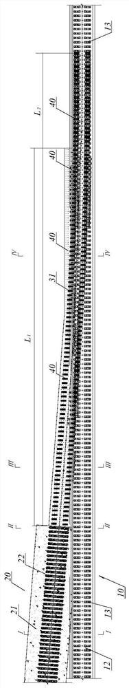
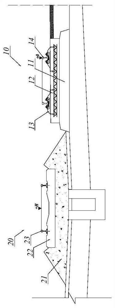
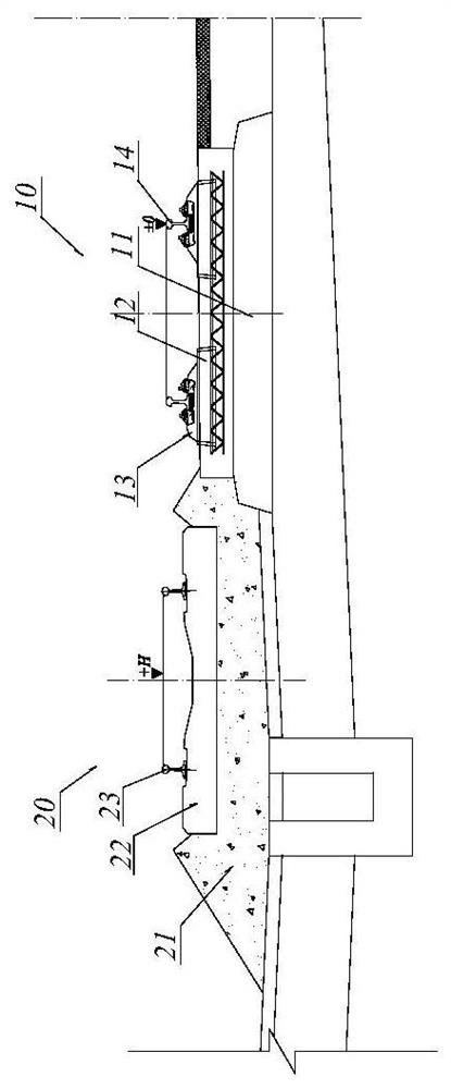
[0021] refer to Figure 1 to Figure 5 , a high-speed railway ballastless track dial connection structure of the present invention, comprising a main line ballastless track 10 and a ballasted track line 20 located on one side thereof. The main line ballastless track 10 includes an existing ballastless track bed 12 located on a supporting layer 11, and an existing double-block sleeper 13 is fixedly arranged on its upper part. The ballasted track toilet line 20 is composed of a ballasted track bed 21 and a sleeper 22, and a transition section L is set between the main line ballastless track 10 and the ballasted track toilet line 20 1 As the basis for transitional dialing of the convenience line, the transition section L 1 The main body is the reinforced concrete widened track bed 30 poured on the outside of the existing ballastless track bed 12 . The tr...


PUM


Abstract

The invention relates to a high-speed railway ballastless track shifting connection structure, and aims at shortening the construction time of a shifting connection foundation to the greatest extent and laying a solid foundation for shifting connection of a main line ballastless track in one skylight time after station off-line foundation diseases are thoroughly treated. The structure comprises amain line ballastless track and a ballasted track temporary line located on one side of the main line ballastless track, wherein the ballasted track temporary line is composed of a ballasted track bedand sleepers, a transition section is arranged between the main line ballastless track and the ballasted track temporary line to serve as a temporary line transition shifting connection foundation, and a main body of the transition section is a reinforced concrete widened track bed poured on the outer side of the ballasted track bed; a certain length in front of the transition section and the main line ballastless track is a track surface elevation lifting section, a split mounting type track bearing table is fixedly arranged on the top faces of the existing ballastless track bed and the reinforced concrete widened track bed in the track surface elevation lifting section, the temporary line steel track is locked through the split mounting type rail bearing table, geometrical shape and position arrangement is conducted on the track surface, and temporary line shifting connection is completed.

Description

technical field [0001] The invention relates to rail transportation, in particular to a high-speed railway ballastless track connection structure. Background technique [0002] In order to completely rectify the basic defects of the inner and lower lines of the station without interrupting the main line traffic and keep the operation capacity of the whole line unchanged, it is necessary to ensure that the double-line main line bypasses the diseased areas in the station and is smoothly dialed to the station line through convenient lines. According to the plane line shape of the track, the 70m ballastless track of the main line conflicts with the line position of the track line. To realize dial connection, it is necessary to remove the 70m ballastless track of the main track and build a track line with ballast track, which takes at least one working day and cannot meet the requirements Uninterrupted driving needs to be within 4.5 hours of the skylight time, and at the same tim...

Claims


Application Information

Patent Timeline
Patent Type & Authority Applications(China)
IPC IPC(8): E01B33/00E01B1/00E01B2/00
CPCE01B33/00E01B1/002E01B2/00
Inventor 潘自立刘在庆曾加胤李粮余李保友杨明辉张凯葛根荣莫宏愿
Owner CHINA RAILWAY ERYUAN ENG GRP CO LTD
Why Eureka
Try Eureka