
A form design method of reducer

A design method and technology of reducer, applied in the direction of mechanical equipment, transmission device, friction transmission device, etc., to achieve the effect of large transmission torque, low manufacturing cost and high input speed

Active Publication Date: 2021-04-27
深圳市泉锲科技有限公司
View PDF17 Cites 0 Cited by
  • Summary
  • Abstract
  • Description
  • Claims
  • Application Information

AI Technical Summary

Problems solved by technology

[0005] The purpose of the present invention is to provide a forming design method of a reducer, which aims to solve the problem that there is no reducer in the prior art that can not only meet the requirements of simple design structure, miniaturized volume, but also can realize the flexible matching design of the reduction ratio

Method used

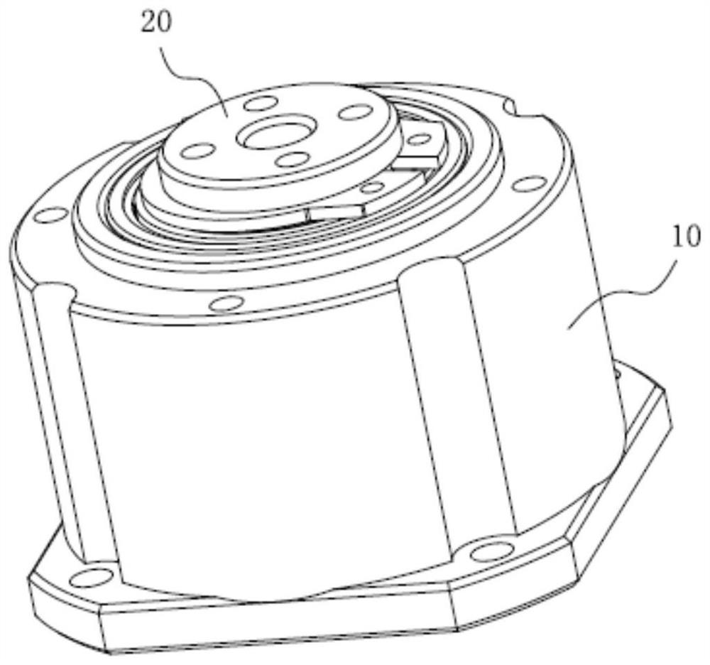
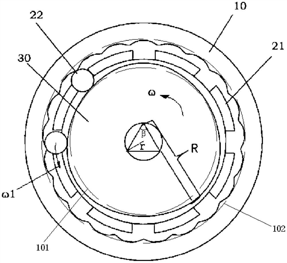

Image

  • A form design method of reducer
  • A form design method of reducer
  • A form design method of reducer

Examples


Embodiment Construction

[0023] Embodiments of the present invention are described in detail below, examples of which are shown in the drawings, wherein the same or similar reference numerals designate the same or similar elements or elements having the same or similar functions throughout. The embodiments described below by referring to the figures are exemplary and are intended to explain the present invention and should not be construed as limiting the present invention.

[0024] In describing the present invention, it should be understood that the terms "length", "width", "upper", "lower", "front", "rear", "left", "right", "vertical", The orientation or positional relationship indicated by "horizontal", "top", "bottom", "inner", "outer", etc. are based on the orientation or positional relationship shown in the drawings, and are only for the convenience of describing the present invention and simplifying the description, rather than Nothing indicating or implying that a referenced device or element...


PUM


Abstract

The invention belongs to the technical field of reducers, and in particular relates to a forming design method of a reducer, comprising the following steps: determining the reduction ratio m, where m is an even number greater than or equal to 4; determining the radius Q of the roller; simulating a roller The movement track of the roller: the driving wheel rotates around the central axis of the driving wheel at an angular velocity ω, and the roller is driven by the driving wheel to rotate around the center of the cross-section of the roller, and the roller is in the same direction as the driving wheel. If the roller revolves around the driving wheel at an angular velocity for one revolution, the roller will form a circle of motion trajectory at the center of the cross section; the points on the motion trajectory line will expand radially by a distance Q with the central axis of the driving wheel as the central axis, The tooth profile of one revolution of the outer ring gear is then formed. The application of this technical solution solves the problem that there is no reducer in the prior art that can not only meet the requirements of simple design structure, miniaturization of volume, but also realize flexible matching design of reduction ratio.

Description

technical field [0001] The invention belongs to the technical field of reducers, in particular to a forming design method of a reducer. Background technique [0002] The reducer is one of the important core components applied to the output end of the power source. At present, the reducers used in robots are mainly RV reducers, harmonic reducers, planetary reducers, worm gear reducers, and reducer mechanisms composed of synchronous belts. The main purpose of the reducer is to convert the high speed and small torque of the power source, reduce a certain speed, and obtain a larger output torque. [0003] In the existing technology, traditional reducers are more difficult to manufacture and have higher manufacturing precision. The representative ones are RV reducers and harmonic reducers; traditional reducers rely heavily on manufacturing materials, such as harmonic reducers The flexible wheel deformation material of the machine; there is a transmission gap in the traditional ...

Claims


Application Information

Patent Timeline
Patent Type & Authority Patents(China)
IPC IPC(8): F16H13/08G06F30/17
CPCF16H13/08G06F30/17
Inventor 刘慧泉谭婧
Owner 深圳市泉锲科技有限公司
Learn More