Angle iron steel seal visual identification system and method assisted by linear lasers

A visual recognition and line laser technology, applied in the field of angle iron steel stamp visual recognition system, can solve the problems of different depths of dents, poor contrast, strong reflection, etc., and achieve the effect of improving the image quality

Pending Publication Date: 2020-11-06
SHANGHAI UNIV
View PDF4 Cites 0 Cited by
  • Summary
  • Abstract
  • Description
  • Claims
  • Application Information

AI Technical Summary

Problems solved by technology

[0005] Due to the different lengths of the codes and the different depths of the dents, the strong reflection and poor contrast of the angle iron stamps; therefore, it is necessary to design an angle iron stamp recognition system that can adapt to this occasion in order to improve the efficiency and accuracy of the stamp code detection. This has become an urgent technical problem to be solved

Method used


Image

  • Angle iron steel seal visual identification system and method assisted by linear lasers
  • Angle iron steel seal visual identification system and method assisted by linear lasers

Examples


Embodiment 1

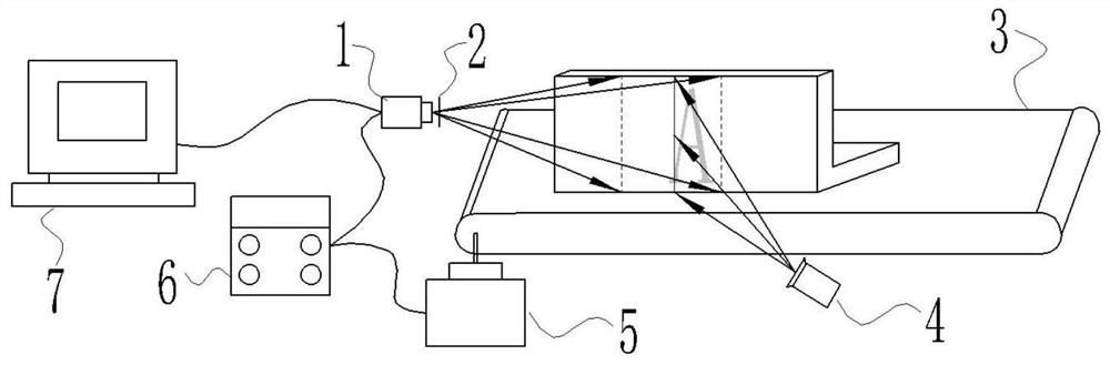
[0042] In this example, see figure 1 , a visual recognition system for angle steel seals that uses line lasers as an auxiliary, including an industrial camera 1, an optical filter 2, a conveyor belt 3, a line laser emitter 4, a motor 5, a controller 6 and an image processing system 7; the industrial The camera 1 is connected to the image processing system 7 through a data transmission interface; at the same time, the industrial camera 1, the motor 5 and the controller 6 are connected to each other to form a closed-loop system. N images are processed, and the line laser stripes in each image are extracted and recombined to form a new image, and then image processing is performed.

Embodiment 2

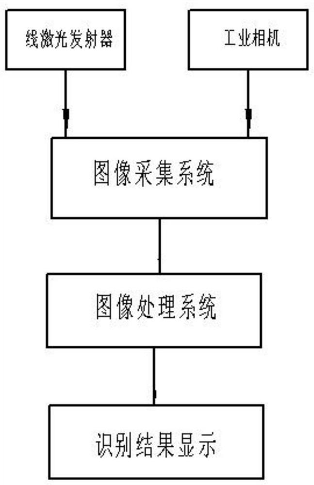
[0044] In this example, see figure 1 and figure 2 , a method for visual recognition of angle iron stencils assisted by a line laser, using the angle iron stencil visual recognition system described in Embodiment 1 to operate, comprising the following steps:

[0045] ① The angle iron moves at a certain speed and passes through the line laser emitted by the line laser transmitter;

[0046] ②The line laser is projected on the angle iron, and the industrial camera takes n images;

[0047] ③ The image processing system processes n images, extracts the line laser stripes in each image and recombines them into a new image;

[0048] ④ Through the recognition and calculation of the curved line laser image, the concave steel stamp on the angle iron is extracted.

Embodiment 3

[0050] This embodiment is basically the same as the above-mentioned embodiment, and the special features are:

[0051]In this embodiment, a method for visual recognition of steel seals on angle irons with the aid of line lasers, in step ②, when the angle irons pass through the line lasers, the n images to be captured by the industrial camera must include Each column on the iron, so there is a certain requirement for the shooting frequency of the industrial camera. Connect the motor of the conveyor belt to the controller. When the precision requirements are high, the output power of the motor can be reduced through the controller to slow down the moving speed of the angle iron. , and at the same time increase the shooting frequency of the industrial camera to effectively acquire the images of each column of the angle iron characters.

[0052] In this embodiment, in step ③, when processing n images containing line lasers, it is necessary to extract the laser lines of each image,...


PUM


Abstract

The invention provides an angle iron steel seal visual identification system and method assisted by linear lasers in order to solve the problems that angle iron steel seals are poor in contrast ratio,steel seal dents are different in depth, steel seal character strings are different in length and the like. An industrial camera and a linear laser emitter are fixedly installed, and the angle iron moves on the conveying belt at a certain speed. When an angle iron steel seal passes through the linear laser, the industrial camera is controlled to shoot a series of images containing the linear laser stripes according to a certain frequency, the linear laser stripes are extracted in each image, and the extracted linear laser stripes are recombined to form a new image. The shooting frequency andthe output power of the motor are adjusted through the controller, and different precision requirements can be met. Because the concave steel seal enables the line lasers to deform locally from the original straight line, image processing is performed on the new image so as to identify the angle iron steel seal. The character extraction aims at the synthesized new image, so that the problems of incomplete one-time photographing and the like caused by overlong steel seal length do not exist, and the method is more suitable for actual requirements.

Description

technical field [0001] The invention relates to the technical field of industrial steel seal coded character recognition, and is mainly characterized by strong reflection, poor contrast and different lengths of coded characters, and specifically relates to a visual recognition system and method for angle iron steel seals with the aid of line lasers. Background technique [0002] Angle irons are widely used in various metal structures, bridges, machinery manufacturing and shipbuilding, various building structures and engineering structures. Before leaving the factory, each angle iron will have a unique corresponding code stamped on one side. However, large quantities of angle irons need to be classified, such as the angle irons of transmission towers, which need to correspond to a specific transmission tower; at the same time, there will inevitably be unqualified quality problems after leaving the factory, and it is necessary to confirm the unqualified product stamps in order ...

Claims


Application Information

Patent Timeline
Patent Type & Authority Applications(China)
IPC IPC(8): G06K9/34
CPCG06V30/153G06V30/10
Inventor 张顺琦汪进超邢宇轩伍宏鹏郑华东夏新星于瀛洁
Owner SHANGHAI UNIV
Why Eureka
Try Eureka