Fuel cell gas flow distribution device and control method

A gas flow and flow distribution technology, applied in fuel cells, electrical components, circuits, etc., can solve the problems of fuel cell system power increase, energy waste, volume, and weight doubled

Active Publication Date: 2020-11-06
CRRC IND INST CO LTD
View PDF10 Cites 0 Cited by
  • Summary
  • Abstract
  • Description
  • Claims
  • Application Information

AI Technical Summary

Problems solved by technology

The purpose of doing this is to ensure sufficient supply of gas participating in the electrochemical reaction in the stack, but it will cause a lot of waste of energy, and the power increase of the fuel cell system will also be affected by the increase in power consumption of auxiliary components such as air compressors, volume, weight, etc. Constrained by factors such as exponential growth

Method used


Image

  • Fuel cell gas flow distribution device and control method
  • Fuel cell gas flow distribution device and control method
  • Fuel cell gas flow distribution device and control method

Examples


specific Embodiment approach

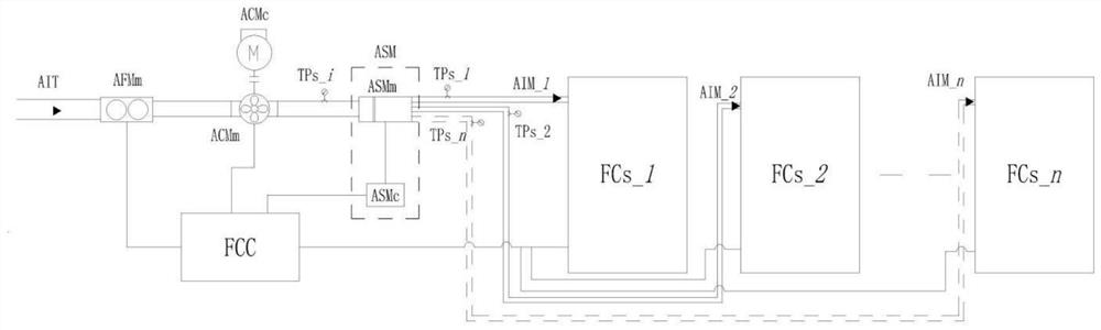
[0105] As mentioned above, the structure of the embodiment of the present invention is obviously different from that of the existing fuel cell power system, and can realize the ability of a single compressor to supply reaction gas to multiple stacks at the same time. The specific implementation method is:

[0106] (1) Under the condition that the external power supply is stable and the hydrogen supply pressure of the fuel cell is normal, the FCc is activated, and the fuel cell power system control unit (i.e. the master controller) starts to work, and the FCc controls the power-on of AFMm, ACMc and ASMc.

[0107] (2) After the ASMc is powered on, first determine the position of the rotating blade CP in the ASMm. If the rotating blade CP is at the preset position, it can ensure that there is no reactive gas remaining in the fuel cell stack and the pipeline of the intake branch pipe. After confirming that the pipeline is in the closed position, ASMc drives ASMm to start working, ...


PUM

PropertyMeasurementUnit
power consumptionaaaaaaaaaa
thicknessaaaaaaaaaa

Abstract

The embodiment of the invention provides a fuel cell gas flow distribution device and a control method. The fuel cell gas flow distribution device comprises a mass flow meter which is used for measuring the actual mass flow of reaction gas in a gas inlet manifold, a pressurization module which is used for increasing pressure for reaction gas in the gas inlet manifold to enable the reaction gas toenter the flow distribution module, a master controller which is used for sending a preset signal to the flow distribution module,and aflow distribution module which is used for determining a corresponding preset control strategy according to the preset signal, so that the flow distribution module is only communicated with one target air inlet branch pipe each time, and circularly and repeatedly inflates each air inlet branch pipe. According to the embodiment of the invention, reaction gas is alternately provided for each fuel cell stack through the flow distribution module, so that the function of simultaneously providing the reaction gas for a plurality of fuel cell stacks through one compressor is realized, and the auxiliary power consumption and the cost of a fuel cell power system arereduced; the problems of energy loss and waste are solved, and the efficiency of a fuel cell power system is improved.

Description

technical field [0001] The invention relates to the technical field of batteries, in particular to a fuel cell gas flow distribution device and a control method. Background technique [0002] In recent years, fuel cell technology has developed rapidly, especially stack technology, plate technology and catalyst technology. The stack power is gradually increased, and the power density is also increased. In terms of system, the volume of fuel cell power system is gradually reduced, and the system integration level is greatly improved. Therefore, the application prospect of fuel cell power system in the field of transportation vehicles is very broad. [0003] With the rapid increase in fuel cell power, the air demand on the cathode side of the stack has also increased significantly. In order to ensure the normal and efficient electrochemical reaction inside the stack, the current high-power fuel cells need to be equipped with an air booster device to ensure sufficient gas con...

Claims


Application Information

Patent Timeline
Patent Type & Authority Applications(China)
IPC IPC(8): H01M8/04746H01M8/04992
CPCH01M8/04753H01M8/04992Y02E60/50
Inventor 张擘刘佰博齐洪峰李明高
Owner CRRC IND INST CO LTD
Why Eureka
Try Eureka