Solidification heat utilization and pollution preventing device for surface water source heat pump

A surface water source heat pump and solidification heat technology, applied in heat pumps, heat exchanger shells, indirect heat exchangers, etc., can solve the problems of high heat energy consumption, large energy consumption, and system instability, and achieve low auxiliary energy consumption, Improve heat transfer efficiency and enhance the effect of water flow disturbance

Inactive Publication Date: 2008-07-09
HARBIN INST OF TECH
View PDF7 Cites 0 Cited by
  • Summary
  • Abstract
  • Description
  • Claims
  • Application Information

AI Technical Summary

Problems solved by technology

[0004] The purpose of the present invention is to solve the problems of the existing surface water source heat pump system solidification heat utilization, the system is unstable by using the hot melt method, it needs to consume part of the high-level heat energy, the overall efficiency is low, and the process is complicated; A surface water source heat pump system solidification heat utilization and anti-pollution device provided for the problems of complex structure, high cost, and large energy consumption

Method used


Image

  • Solidification heat utilization and pollution preventing device for surface water source heat pump
  • Solidification heat utilization and pollution preventing device for surface water source heat pump
  • Solidification heat utilization and pollution preventing device for surface water source heat pump

Examples


specific Embodiment approach 1

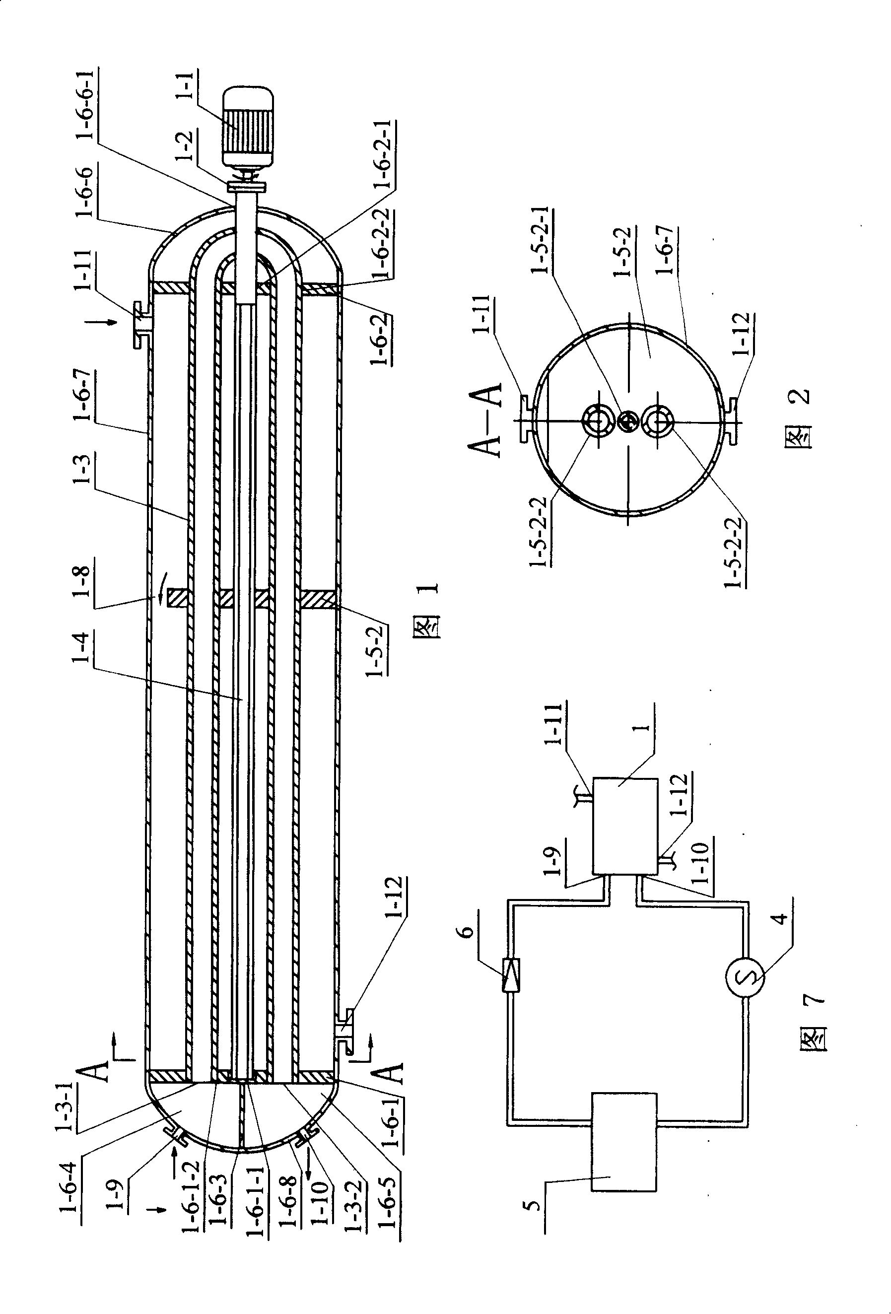
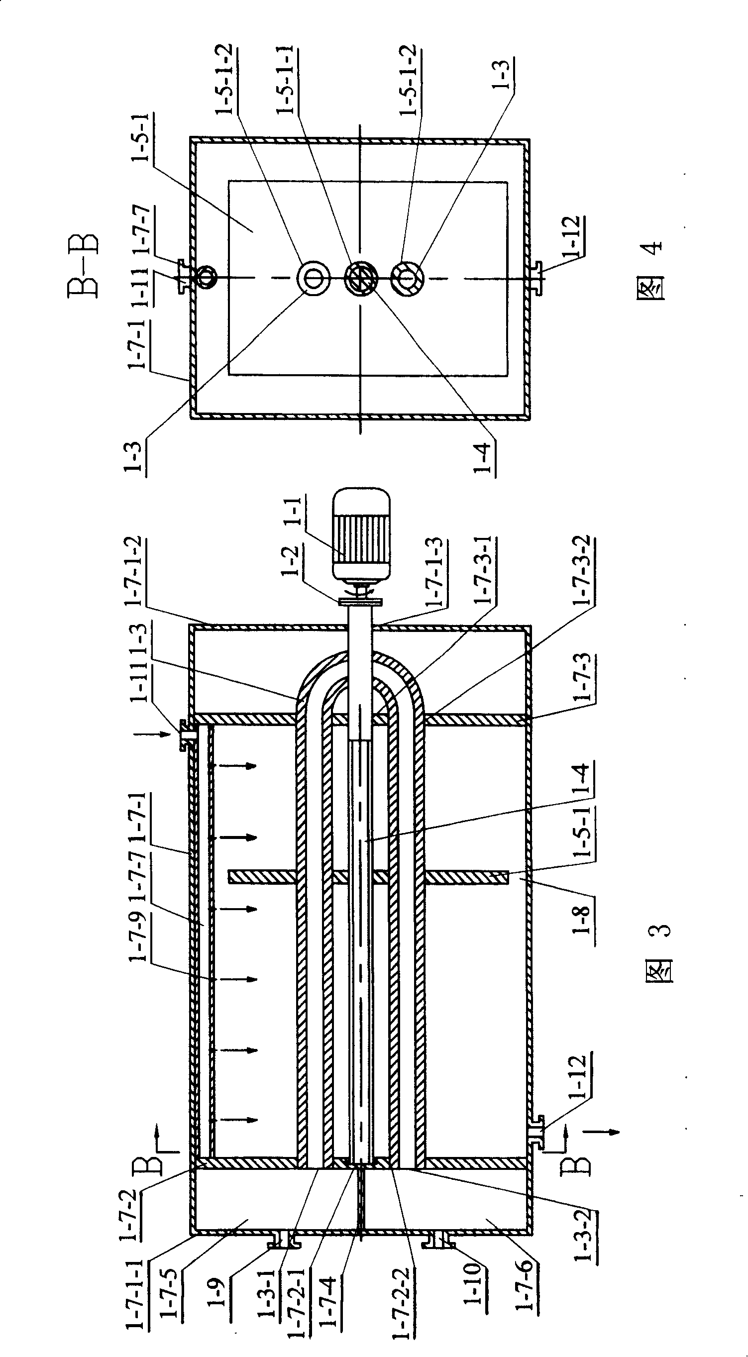
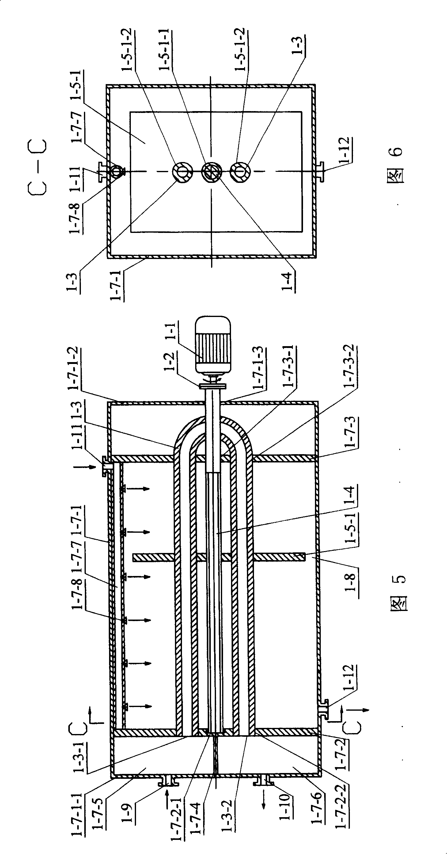
[0008] Specific embodiment 1: Combining Fig. 1, Fig. 2, Fig. 3, Fig. 4, Fig. 5, Fig. 6, Fig. 7 illustrates this embodiment, this embodiment is composed of heat exchanger 1, compressor 4, expansion valve 6, condenser 5; the heat exchanger 1 is composed of a motor 1-1, a reducer 1-2, a heat exchange tube 1-3, a screw 1-4, an orifice plate, and a shell; one end of the screw 1-4 is along the shell The length direction is installed in the shell, the screw 1-4 installed in the shell is equipped with an orifice plate which is threadedly connected with the screw 1-4, and there are water flow channels 1-8 and screw 1-4 between the orifice plate and the inner wall of the shell. The other end is connected to the output shaft of the motor 1-1 through the reducer 1-2, the heat exchange tube inlet 1-3-1 passes through the heat exchange carrier inlet cavity or enters the cavity and the heat exchange carrier inlet 1-9 on the shell The heat exchange tube outlet 1-3-2 is connected to the heat excha...

specific Embodiment approach 2

[0013] Second embodiment: This embodiment will be described with reference to FIG. 11. The difference between this embodiment and the first embodiment is that the screw 1-4 in the housing of this embodiment is equipped with a set of orifice plates that are threadedly connected with the screw 1J. With the above structure, work efficiency can be improved. Other components and connection relationships are the same as in the first embodiment.

specific Embodiment approach 3

[0014] Specific embodiment three: This embodiment will be described with reference to Figure 1, Figure 2, and Figure 11. The difference between this embodiment and the first embodiment is: the case of this embodiment is a cylindrical case; the cylindrical case The body is composed of a cylindrical shell, a first fixed plate 1-6-1, a second fixed plate 1-6-2 and a partition 1-6-3; the cylindrical shell is composed of a cylindrical cylinder 1-6- 7 and the first head 1-6-8 and the second head 1-6-6 welded to the two ends of the cylindrical cylinder 1-6-7 respectively; the first fixed plate 1-6-1 and the second The fixed plates 1-6-2 are respectively installed on the two ends of the cylindrical cylinder 1-6-7 and welded to the inner wall of the cylindrical cylinder 1-6-7. The first fixed plate 1-6-1 is provided with There are concave holes 1-6-1-1, the second fixing plate 1-6-2 is provided with a center hole 1-6-2-1, and the second head 1-6-6 is provided with the center The hole 1-6-2...


PUM


Abstract

The invention relates to a ground water heat pump system solidified heat utilization and anti-pollution device, which can solve the defects of present product that uses the hot melt method with complex process and uses the mechanical vibration to remove ice with large energy consumption. In said invention, one end of screw bolt (1-4) is mounted inside the case along the length of case, while it comprises at least one porous plate connecting the screw of them; another end of screw bolt (1-4) via the speed reducer (1-2) is connected to the motor (1-1) and through the heat exchange pipe inlet (1-3-1) is connected to the heat exchange carrier inlet (1-9) of case, and through the heat exchange outlet (1-3-2) of porous plate is connected to the heat exchange carrier outlet (1-10) of case, while the case has a water inlet (1-11) and a water outlet (1-12). The invention uses the ground water solidified heat to attain ice, uses the oscillating motion of porous plate to remove the ice and dirt, with simple structure, lower cost and high heat exchange efficiency.

Description

Technical field [0001] The invention relates to a device for utilizing solidification heat of a water source heat pump system. Background technique [0002] The development and utilization of various low-level renewable clean energy sources as heat pump cold and heat sources provide energy for building heating and air conditioning, while also having important energy saving and environmental protection significance. Water sources such as rivers, rivers, lakes, sea water, and urban sewage are good low-level energy sources. They are abundant in quantity, widely distributed, and have huge potential heat energy. Compared with air sources, they not only have higher heat capacity, but also have relatively warm winter and cool summer. Thermal properties. The heat pump heating coefficient is 30% higher than that of the air source, and it has a higher heat transfer efficiency than the soil source. The heat pump system has high efficiency and low initial investment. Compared with the ground...

Claims


Application Information

Patent Timeline
Patent Type & Authority Patents(China)
IPC IPC(8): F28D7/10F28F9/00F28F17/00F25B30/06
Inventor 吴荣华孙德兴
Owner HARBIN INST OF TECH
Why Eureka
Try Eureka