Man-machine engineering mechanical arm for rehabilitation training

An ergonomic, robotic arm technology, applied in passive exercise equipment, physical therapy and other directions, can solve the problems of inconvenience, patient safety, and inability to achieve flexible control, and achieve the effect of ease of use and burden reduction.

Inactive Publication Date: 2020-11-10
CHANGZHOU INST OF MECHATRONIC TECH
View PDF6 Cites 1 Cited by
  • Summary
  • Abstract
  • Description
  • Claims
  • Application Information

AI Technical Summary

Problems solved by technology

The current products mainly have the following deficiencies: first, most of the current upper limb rehabilitation structures cannot be flexibly controlled, and do not match the movement of human upper limb joints; second, the existing rehabilitation institutions

Method used


Image

  • Man-machine engineering mechanical arm for rehabilitation training
  • Man-machine engineering mechanical arm for rehabilitation training
  • Man-machine engineering mechanical arm for rehabilitation training

Examples


Embodiment 1

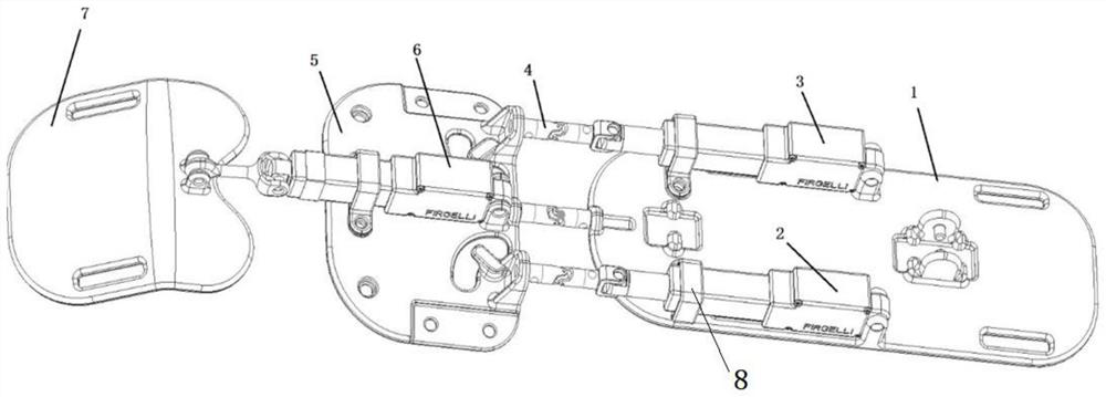
[0022] An ergonomic mechanical arm for rehabilitation training, including a forearm board 1, a first linear actuator A2, a second linear actuator B3, a universal joint mechanism 4, a palm board 5, a third linear actuator C6 and fingers plate 7.

[0023] The first linear actuator A2 and the second linear actuator B3 are arranged in parallel, and the ends of the two actuators are floatingly connected to the ear seat on the forearm plate 1 through pins; the U-shaped limit 8 is located on the actuators A and B , the middle part of C, and there is a gap between the actuator to limit the large-scale rotation of the mechanism and ensure safety. The other ends of the first linear actuator A2 and the second linear actuator B3 pass through the universal joint structure 4 and the palm plate 5 respectively. The ear sockets are connected; the third linear actuator C6 is located at the symmetrical center of the palm plate 5, and the end is connected to the forearm plate 1 through the third ...

Embodiment 2

[0026] The composition of this mechanical arm is as follows figure 1 As shown, it includes a linkage mechanism operated by three linear actuators to facilitate hand, wrist and forearm exercises. During use, the soft wrist strap is worn on the patient's forearm through the two slots at the rear of the forearm board 1. The palm board 5 is located at the back of the patient's hand. The forearm board 1 is floatingly connected with the palm board 5 through the universal joint mechanism 4. Through the groove on the finger plate 7, it is connected with the patient's finger.

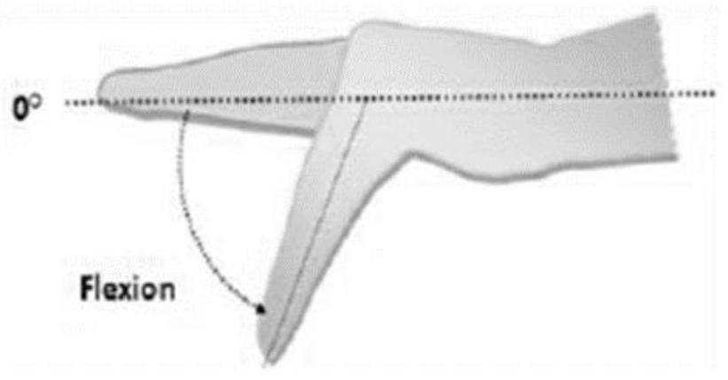
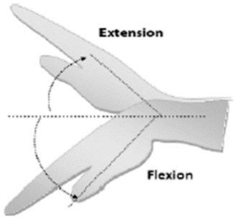
[0027] Two linear actuators on the forearm board 1 assist the wrist to realize the flexion-extension movement and flexion-ulnar deviation movement. When the linear actuators 1 and 2 are fully extended or half extended, the flexion-extension movement of the wrist is realized, such as Figure 2b As shown; when one of the linear actuators is fully extended and the other linear actuator is fully contracted, the fl...


PUM


Abstract

The invention belongs to the technical field of rehabilitation devices, and relates to a man-machine engineering mechanical arm for rehabilitation training. The mechanical arm comprises a front arm plate, a first linear actuator A, a second linear actuator B, universal joint mechanisms, a palm plate, a third linear actuator C and a finger plate; the first linear actuator A and the second linear actuator B are arranged in parallel, and the tail ends of the two actuators are in floating connection with lugs on the front arm plate through pins; U-shaped limiting parts are located in the middles of the actuators A, B and C, and gaps are reserved between the U-shaped limiting parts and the actuators; and the other ends of the first linear actuator A and the second linear actuator B are connected with lugs on the palm plate through the universal joint structures. The mechanical arm is suitable for clinic, and also suitable for home rehabilitation training, and burdens of patients and rehabilitation physicians are reduced; and the flexion and extension movement of fingers except for a thumb, the flexion and extension movement of a wrist and the scratch and ulnar deviation movement can berealized.

Description

technical field [0001] The invention belongs to the technical field of rehabilitation devices, and relates to an ergonomic mechanical arm used for rehabilitation training. Background technique [0002] Stroke, also known as apoplexy, has the characteristics of high morbidity, high mortality and high disability rate. Stroke patients may experience a variety of neurological deficits, among which hemiplegia and movement disorders are the most common. However, hand dysfunction in patients with upper limb disabilities is often clinically manifested as flexion contracture, decreased muscle strength, abnormal muscle tone, decreased finger flexibility, numbness of the limbs, decreased range of motion of the thumb, precise grasping and pinching, lateral pinching, decreased joint movement coordination, Reduced strength coordination, etc., will also lose part of the tactile perception and proprioceptive functions, and lose the feedback perception of movement. [0003] Rehabilitation ...

Claims


Application Information

Patent Timeline
IPC IPC(8): A61H1/02
CPCA61H1/0274A61H1/0285A61H1/0288A61H2205/06A61H2205/065A61H2205/067A61H2201/1638A61H2201/1659A61H2201/165
Inventor 靳敏吴小邦杜茵毛阿虎许立波
Owner CHANGZHOU INST OF MECHATRONIC TECH
Why Eureka
Try Eureka