
Driven bevel gear drilling device

A drilling device and bevel gear technology, which is applied in the field of machining, can solve the problems of easy wear and tear of the bottom plate, time-consuming and labor-intensive, inability to realize an automatic production line, etc., and achieves the effects of convenient disassembly and refurbishment, not easy to wear, and easy to install and disassemble.

Pending Publication Date: 2020-11-10
GUILIN FUDA GEAR
View PDF0 Cites 0 Cited by
  • Summary
  • Abstract
  • Description
  • Claims
  • Application Information

AI Technical Summary

Problems solved by technology

This tool has the following disadvantages: the workpiece is directly placed on the base plate, which makes the base plate easy to wear, and it is time-consuming and laborious to remove all the tooling when repairing the base plate; the tooling is manually clamped, and the clamping and loosening of the workpiece are manually tightened, To complete by loosening the lock nut, the establishment of an automated production line cannot be realized

Method used


Image

  • Driven bevel gear drilling device

Examples


Embodiment

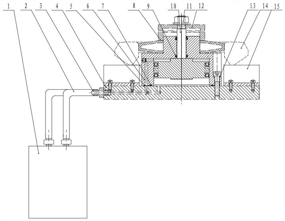
[0014] Such as figure 1 As shown, a driven bevel gear drilling device consists of a hydraulic station 1, a high-pressure oil pipe 2, a pipe joint 3, a bottom plate 4, a sealing ring 5, an oil cylinder body 6, a sealing ring 7, a compression ring 8, and a piston ring sealing ring 9. The piston rod 10, the lock nut 11, the gland 12, the spring washer 13, the workpiece 14 and the spacer 15 are composed, the piston rod 10 is installed on the oil cylinder body 6, and the oil cylinder body 6, the pipe joint 3 and the spacer 15 are fixed on the bottom plate 4; the base plate 4 is respectively provided with an oil inlet hole and an oil outlet hole, the oil inlet hole and the oil outlet hole are respectively connected with the high-pressure oil pipe 2 through the pipe joint 3, and the high-pressure oil pipe 2 is connected with the hydraulic station 1, and the spring expands, presses The inner hole of the tight ring 8 cooperates with the positioning shaft diameter of the oil cylinder bo...


PUM


Abstract

The invention discloses a driven bevel gear drilling device. The driven bevel gear drilling device comprises a hydraulic station, a high-pressure oil pipe, a pipe joint, a bottom plate, an oil cylinder body, cushion blocks, a spring expansion piece, a pressing ring, a gland, a piston rod and a lock nut. The driven bevel gear drilling device is characterized in that the piston rod is arranged in the oil cylinder body, and the oil cylinder body, the pipe joint and the cushion blocks are fixed to the bottom plate; the bottom plate is provided with an oil inlet and an oil outlet and connected to the hydraulic station through the high-pressure oil pipe and the pipe joint; and inner holes of the spring expansion piece and the pressing ring are matched with the positioning shaft diameter of the oil cylinder body, and sleeve the oil cylinder body; and the gland and the lock nut sleeve the piston rod. The driven bevel gear drilling device adopts a hydraulic clamping mode, is convenient to assemble and disassemble, and can realize automatic production of a drilling procedure.

Description

technical field [0001] The invention relates to machining technology, in particular to a driven bevel gear drilling device. Background technique [0002] At present, when machining the driven bevel gear hole group, the tooling structure used consists of a bottom plate, a limit block, a spring expansion piece, a gland, a screw rod and a lock nut. During processing, the lock nut is tightened, and the gland is forced by the spring expansion sheet, so that the spring expansion sheet is stretched, thereby clamping the inner hole of the bevel gear for processing. This tool has the following disadvantages: the workpiece is directly placed on the base plate, which makes the base plate easy to wear, and it is time-consuming and laborious to remove all the tooling when repairing the base plate; the tooling is manually clamped, and the clamping and loosening of the workpiece are manually tightened, To complete by loosening the lock nut, the formation of an automated production line ca...

Claims


Application Information

Patent Timeline
Patent Type & Authority Applications(China)
IPC IPC(8): B23B41/00B23B47/00B23Q3/08
CPCB23B41/00B23B47/00B23Q3/082
Inventor 庞雄南农小锐全玉琼黄千洪
Owner GUILIN FUDA GEAR
Learn More