Rapid supporting structure for tunnel guide wall formwork and construction method

A technology of supporting structure and construction method, applied in the direction of formwork/formwork/work frame, formwork/formwork/work frame connector, tunnel, etc., can solve the problem of uneven force on the bottom formwork of the guide wall and increase the difficulty of management , increase in construction costs, etc., to achieve the effect of ensuring quality linear control, reducing equipment investment, and reducing equipment investment

Pending Publication Date: 2020-11-10
ROAD & BRIDGE INT +1
View PDF9 Cites 0 Cited by
  • Summary
  • Abstract
  • Description
  • Claims
  • Application Information

AI Technical Summary

Problems solved by technology

[0003] The conventional construction method adopts bowl buckle scaffolding for erection. Due to the narrow tunnel opening and effective construction space, the installation of scaffolding is not conducive to formwork support, which may easily cause formwork explosion, so it cannot be used.
[0004] Disadvantages of the conventional construction method: 1) The core soil is reserved in the ring direction of the tunnel to construct the guide wall. The installation of the steel pipe bowl support is limited by the site terrain, and the corresponding spacing cannot be arranged at equal intervals. The force on the bottom formwork of the guide wall is uneven, and uneven Uniform settlement, the construction quality of the guide wall cannot be guaranteed, which is not conducive to project quality control; 2) The steel pipe bowl scaffolding needs to be leased or purchased, and there are many vulnerable components, and the corresponding components are easy to be lost due to poor management, which increases the difficulty of management and increases the construction cost; 3 ) The connection of the steel pipe bowl scaffolding relies on fastener-type connections, and there is a lot of human interference. The stability of the bowl scaffolding during the construction process is not good, and it is prone to collapse and other unsafe hazards; Mutual interference, slow construction progress

Method used


Image

  • Rapid supporting structure for tunnel guide wall formwork and construction method

Examples


Embodiment Construction

[0027] In order to enable those skilled in the art to better understand the solution of the present application, the technical solution in the embodiment of the application will be clearly and completely described below in conjunction with the accompanying drawings in the embodiment of the application. Obviously, the described embodiment is only It is an embodiment of a part of the application, but not all of the embodiments. Based on the embodiments in this application, all other embodiments obtained by persons of ordinary skill in the art without creative efforts shall fall within the scope of protection of this application.

[0028] It should be noted that the terms "first" and "second" in the specification and claims of the present application and the above drawings are used to distinguish similar objects, but not necessarily used to describe a specific order or sequence. It should be understood that the data so used may be interchanged under appropriate circumstances for ...


PUM


Abstract

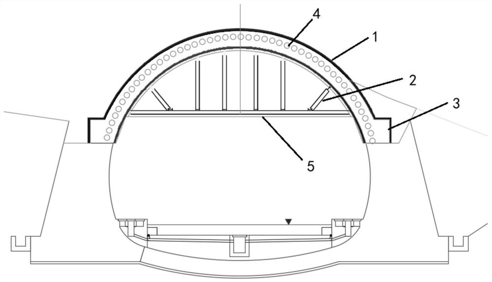
The invention discloses a rapid supporting structure for a tunnel guide wall formwork and a construction method. The rapid supporting structure comprises a guide wall and a supporting system; a guidepipe is arranged in the guide wall, the inclination angle of the guide pipe is 1-3 degrees, and arch feet are arranged at the two ends of the guide wall; and the supporting system comprises a transverse supporting pipe and an oblique supporting pipe, and the two ends of the oblique supporting pipe are connected with the transverse supporting pipe and the guide wall respectively. According to the construction method, potential safety hazards in the installation process of a steel pipe bowl opening scaffold are avoided, equipment investment is reduced, the utilization rate of existing materialsis increased, the construction cost is saved, and the construction period is shortened; and the outstanding effects of high safety, high economy and high construction speed are achieved.

Description

technical field [0001] The invention belongs to the field of tunnel engineering in the railway industry, and is applied to the installation of formwork for a guide wall of a tunnel, and in particular relates to a structure and a construction method for installing and supporting a formwork for a guide wall of a tunnel. Background technique [0002] With the continuous development of my country's railway industry, the demand for railway construction continues to grow. The surrounding space of the railway tunnel is narrow, and the formwork bracket and support system are too small to store too much in the car yard. They need to be processed and installed in advance. Due to the limitation of the terrain of the tunnel entrance, how to quickly install the support on the guide wall formwork and improve the construction progress is Problems that need to be solved urgently. [0003] The conventional construction method adopts bowl buckle scaffolding for erection. Due to the narrow tu...

Claims


Application Information

Patent Timeline
Patent Type & Authority Applications(China)
IPC IPC(8): E21D11/10E04G11/08E04G17/14
CPCE21D11/10E04G11/08E04G17/14
Inventor 张瑞平邱伟超王玮沈文祝金树坤贾永泉
Owner ROAD & BRIDGE INT
Why Eureka
Try Eureka