
Wave energy power generation device

A technology of power generation device and ocean wave energy, which is applied in ocean energy power generation, engine components, machines/engines, etc., can solve the problems of high cost, difficult to popularize and apply, and low efficiency of ocean wave energy.

Inactive Publication Date: 2020-11-10
梅宝东
View PDF6 Cites 0 Cited by
  • Summary
  • Abstract
  • Description
  • Claims
  • Application Information

AI Technical Summary

Problems solved by technology

Because the wave energy per unit area is not strong enough, the efficiency of wave power generation is low, the cost is high, and it is difficult to popularize and apply

Method used


Image

  • Wave energy power generation device
  • Wave energy power generation device
  • Wave energy power generation device

Examples


Embodiment 1

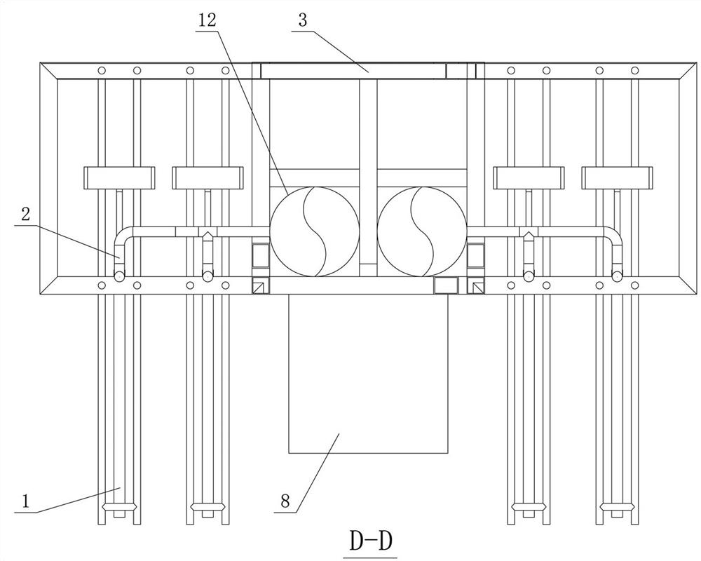
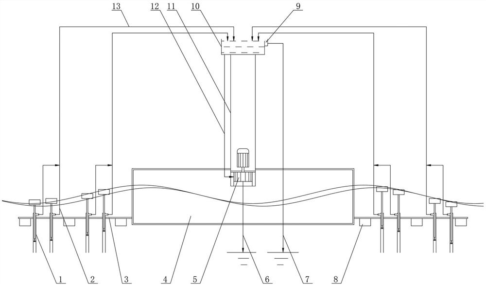
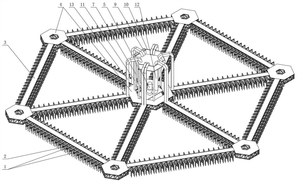
[0030] Such as figure 1 , figure 2 , image 3 , Figure 4 with Figure 5 As shown, a wave energy power generation device includes a water pump (1), a water pump outlet pipe (2), a floating bridge (3), a floating island group (4), a high-level pool inlet pipe (13), and a high-level pool bracket (11), overflow pipe (7), hydro-generator unit (5), overflow tank (9), high-level pool (10), water-turbine-generator unit inlet pipe (12), hydro-generator unit draft pipe (6 ) and pontoon (8). The water absorber (1) transfers the mechanical energy available in the waves to the seawater flowing through the water absorber (1), and this part of the seawater that has absorbed the mechanical energy in the waves is pumped to the high level pool (10) after summarization. Then it flows downward through the water turbine generator set inlet pipe (12) and the water turbine generator set (5) to convert mechanical energy into electrical energy. The buoyancy tank (8) is used to adjust the buoya...

Embodiment 2

[0047] Such as Image 6 , Figure 7 , Figure 8 , Figure 9 with Figure 10 As shown, a wave energy power generation device includes a water pump (1), a water pump outlet pipe (2), a floating bridge (3), a floating island group (4), a hydroelectric generator set (5), and a hydroelectric generator The water inlet pipe (12) of the unit, the draft pipe (6) of the hydro-generator set and the buoyancy tank (8). The water absorber (1) transfers the mechanical energy available in the waves to the seawater flowing through the water absorber (1), and this part of the seawater that absorbs the mechanical energy in the waves is collected and then pumped to the hydroelectric generator set (5) to convert mechanical energy into electrical energy. The buoyancy tank (8) is used to adjust the buoyancy force suffered by the whole device, and the quantity and size etc. are determined according to actual needs.

[0048] The structural dimensions and parameters of a kind of wave energy gener...


PUM

PropertyMeasurementUnit
Inscribed circle diameteraaaaaaaaaa
Circumcircle diameteraaaaaaaaaa

Abstract

The invention discloses a wave energy power generation device. According to the device, energy of sea waves is utilized to gather a small amount of seawater together to form a large flow and a large water head to drive a water turbine generator set to generate electricity. The device comprises a floating island group, water drawing devices, floating bridges, floating boxes, water conveying pipelines and the water turbine generator set, wherein the floating island group comprises a central floating island and satellite floating islands and can stably float on the sea surface, the floating islands are connected with one another through the floating bridges, an elevated water tank and the water turbine generator set are installed on the central floating island, and the elevated water tank islocated above the water turbine generator set; the large number of water drawing devices are installed on the two sides of the floating bridges and the peripheries of the floating islands, and along with fluctuation of the sea waves, the water drawing devices continuously gather the seawater into the elevated water tank; the seawater in the elevated water tank flows downwards through the water turbine generator set, and mechanical energy is converted into electric energy; and the floating boxes are used for adjusting buoyancy borne by the whole device.

Description

technical field [0001] The invention relates to the field of ocean development, in particular to the field of ocean wave power generation. Background technique [0002] Ocean waves contain abundant mechanical energy, which is widely distributed, clean and pollution-free. The development and utilization of ocean wave energy is of great significance for increasing global energy supply and reducing environmental pollution. Coastal countries all over the world are vigorously advocating the utilization and development of wave energy. [0003] At present, there are many technologies for generating electricity using ocean wave energy. The main principle of these technologies is to use various methods to convert the kinetic energy of the up and down motion of sea surface waves into electrical energy. Because the wave energy per unit area is not strong enough, the efficiency of wave power generation is low, the cost is high, and it is difficult to popularize and apply. Contents of...

Claims


Application Information

Patent Timeline
IPC IPC(8): F03B13/14B63B35/44A01K61/60
CPCA01K61/60B63B35/44B63B2035/4466F03B13/144F05B2240/932Y02E10/30Y02P60/60Y02A40/81
Inventor 梅宝东
Owner 梅宝东
Learn More