Magnetic refrigeration device

A magnetic refrigeration and permanent magnet technology, which is applied in refrigerators, refrigeration and liquefaction, magnets, etc., can solve the problem of small air gap for magnetic working medium, limited radial air gap size, refrigeration or heating of magnetic refrigeration devices Low performance and other problems, to achieve the effect of increasing the volume of the air gap, increasing the effective working space, and improving the cooling or heating performance

Pending Publication Date: 2020-11-10
GREE ELECTRIC APPLIANCES INC
View PDF0 Cites 3 Cited by
  • Summary
  • Abstract
  • Description
  • Claims
  • Application Information

AI Technical Summary

Problems solved by technology

[0008] Therefore, the technical problem to be solved by the present invention is to overcome the limited size of the radial air gap in the magnetic refrigeration device in the prior art, which makes the volume o

Method used


Image

  • Magnetic refrigeration device
  • Magnetic refrigeration device
  • Magnetic refrigeration device

Examples


no. 1 approach

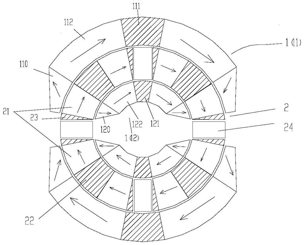
[0077] Such as Figure 1-7 As shown, the first embodiment is described. The magnet constituted by the first embodiment has four magnetic gaps (ie air gap space), and the basic principle of its magnetic circuit can be referred to Figure 14 shown.

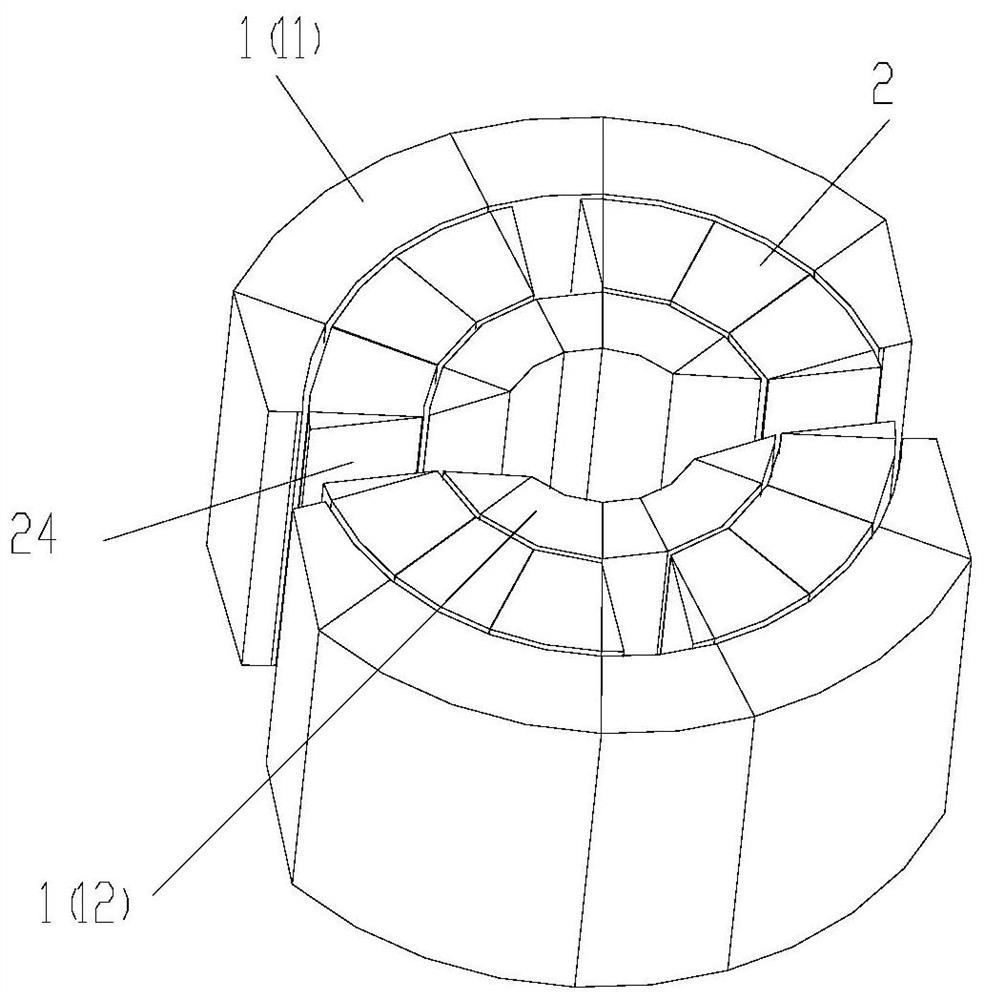
[0078] Such as figure 1 As shown, the magnetic field system is composed of two magnet assemblies, the first assembly 1 and the second assembly 2; the first assembly 1 is composed of 2 first magnet assembly units, and the 2 first magnet assembly units are preferably 360° uniform arrangement; figure 2 As shown, it is a three-dimensional schematic diagram of the first embodiment, and it can be seen that there are four magnetic gaps for placing the magnetic working medium bed 24 .

[0079] Preferably,

[0080] The magnetic force lines of the second magnet assembly are connected in series to form a closed loop. The closed magnetic circuit formed by the second magnet assembly connected in series can effectively increase the magnetic...

no. 2 approach

[0121] Such as Figure 8-9 A second embodiment is shown, which differs from the first embodiment in the first magnet assembly. Such as Figure 8 Shown is a second embodiment.

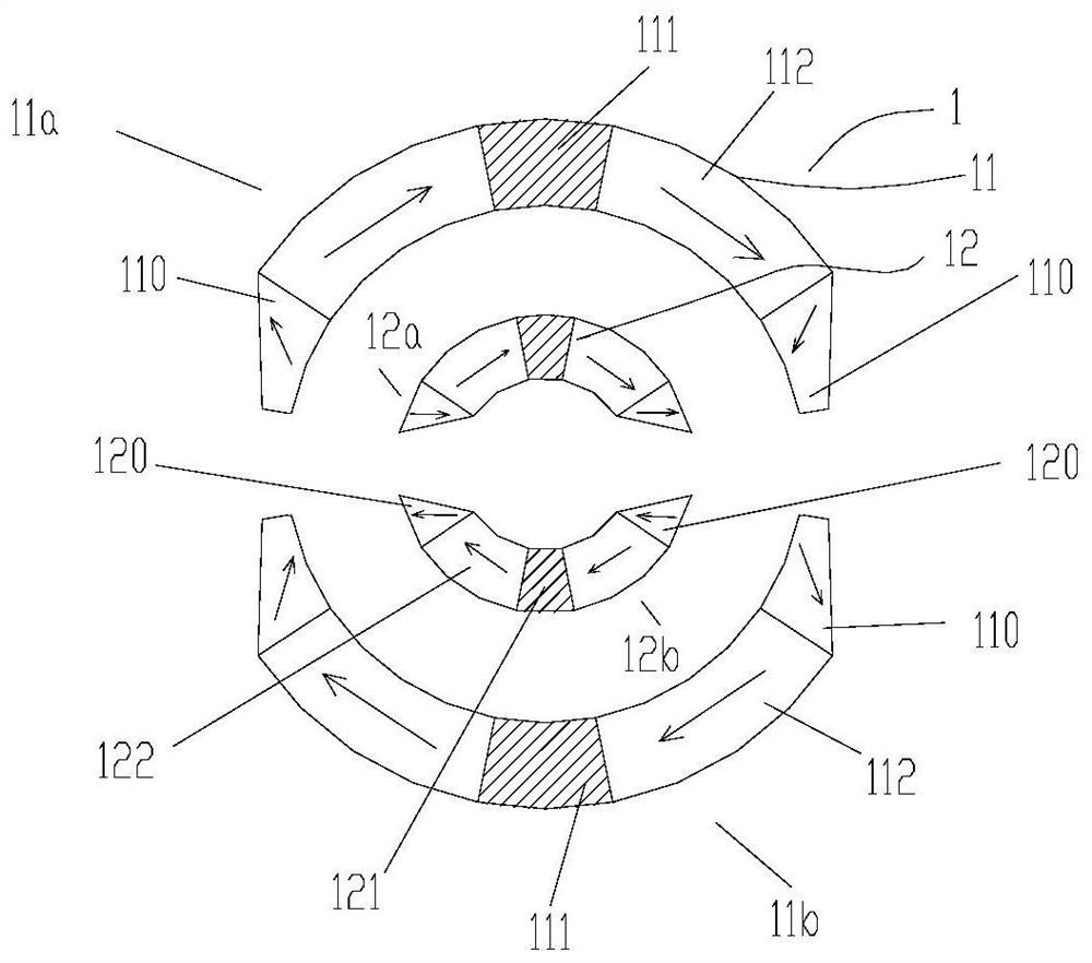
[0122] A schematic diagram of the first magnet assembly in the second embodiment is shown in Figure 9 As shown, the first magnet assembly in the first embodiment is as image 3 shown; image 3 and Figure 9 The difference is that Figure 9 A non-magnetic inner connector 124 and a non-magnetic outer connector 114 are added;

no. 3 approach

[0124] Figure 10-11 Used to describe the third embodiment, Figure 10 The third embodiment represented by and figure 1 The first embodiment shown differs in the second magnet assembly.

[0125] Figure 11 represents a third embodiment of the second magnet assembly and Figure 4 The second magnet assembly of the first embodiment shown differs in that: Figure 11 Each second magnet assembly unit is composed of two second soft magnets 22, a second permanent magnet 21 in the middle, and pole pieces 23 at both ends; the entire second magnet assembly uses four second permanent magnets in total. 21, while Figure 4 Used eight second permanent magnets 21 in. The use of soft magnets instead of permanent magnets can reduce the cost of the magnet system. In addition, the use of soft magnetic materials on both sides of the magnetic working fluid bed is conducive to the aggregation of magnetic circuits and is also conducive to Figure 10-11 The better magnetic shielding effect of t...


PUM


Abstract

The invention provides a magnetic refrigeration device which comprises a first assembly (1) and a second assembly (2). The second assembly (2) is an annular assembly, the first assembly (1) is locatedat the radial outer side or the radial inner side of the second assembly (2), the first assembly (1) is a first magnet assembly, and the second assembly (2) is provided with an air gap space capableof containing a magnetic working medium bed (24). The first assembly (1) and the second assembly (2) can do relative rotation motion, and the magnetic force line direction of the first magnet assemblyis distributed in the circumferential direction of the annular second assembly (2). According to the magnetic refrigeration device, the radial size of the second assembly can be made larger, the containing air gap volume of the magnetic working medium bed is increased, the quantity of magnetic working media or the actual effective working space of magnets is increased, the refrigeration or heating effect of the magnetic refrigeration device is improved, and the refrigeration or heating performance of the magnetic refrigeration device is improved.

Description

technical field [0001] The invention belongs to the technical field of magnetic refrigeration, and in particular relates to a magnetic refrigeration device. Background technique [0002] The invention relates to the field of magnetic refrigeration, and mainly relates to a magnetic field generating device of a rotary magnetic refrigerator. [0003] Magnetic refrigeration technology is a solid-state refrigeration method based on the magnetocaloric effect. It uses water and other environmentally friendly media as the heat transfer fluid. It has the characteristics of zero GWP, zero ODP, intrinsic high efficiency, low noise and low vibration. In the range of room temperature, magnetic refrigeration has a broader application prospect, such as applications in household refrigerators, air conditioners, and medical and health services. Therefore, in the past ten years, the research and development of room temperature magnetic refrigeration technology has been widely valued by count...

Claims


Application Information

Patent Timeline
IPC IPC(8): F25B21/00
CPCF25B21/00F25B2321/0023Y02B30/00F25B2321/0022H01F7/021H01F7/0273
Inventor 汪魁罗胜杨蓉
Owner GREE ELECTRIC APPLIANCES INC
Why Eureka
Try Eureka