Raman light phase noise testing method and system based on cold atom interference

A technology of phase noise and test method, applied in optical radiation measurement, measurement device, measurement optics, etc., can solve the problem of lack of self-calibration function and other problems

Active Publication Date: 2020-11-10
NAT UNIV OF DEFENSE TECH
View PDF6 Cites 2 Cited by
  • Summary
  • Abstract
  • Description
  • Claims
  • Application Information

AI Technical Summary

Problems solved by technology

[0005] The present invention provides a Raman optical phase noise testing method and system based on atomic interference, which is used to overcome defects such as the lack of self-calibration function in the prior art, and has potential high-accuracy characteristics, through the sensitive response of atoms to phase jitter , realize the test of Raman optical phase noise based on cold atom interferometry technology, compared with the traditional signal analyzer test, it has the function of self-calibration

Method used


Image

  • Raman light phase noise testing method and system based on cold atom interference
  • Raman light phase noise testing method and system based on cold atom interference
  • Raman light phase noise testing method and system based on cold atom interference

Examples


Embodiment 1

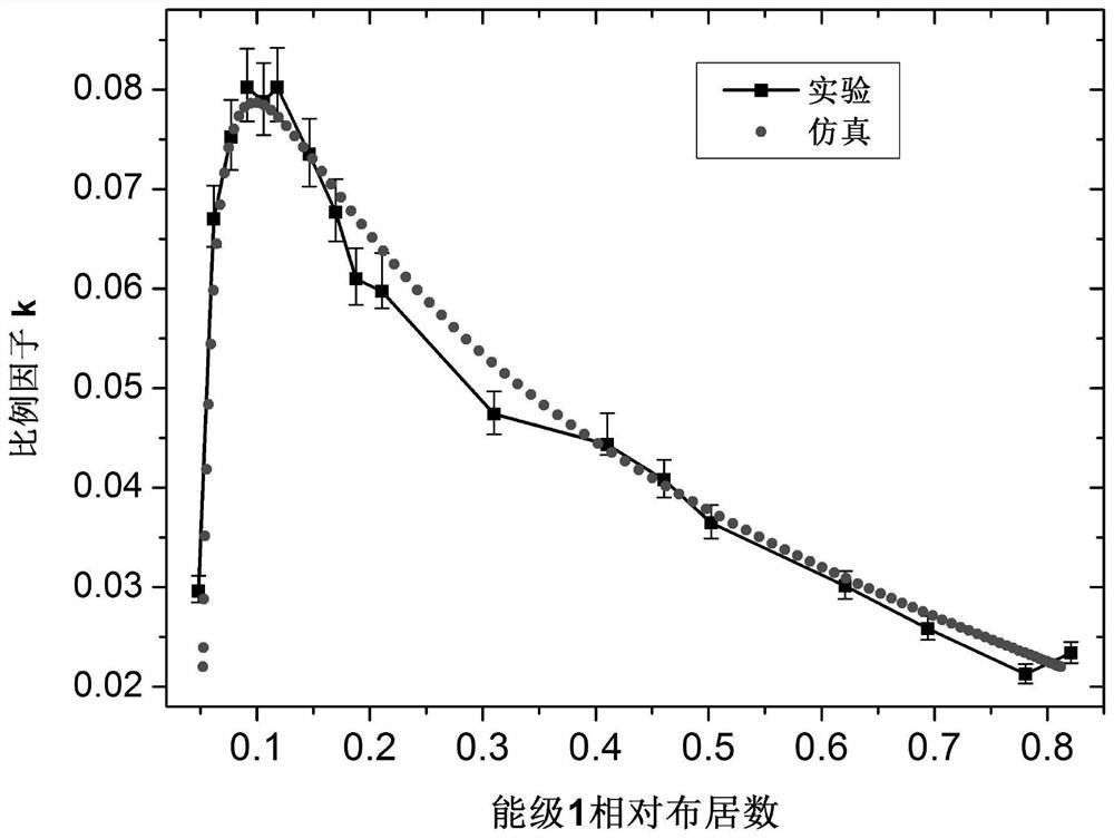
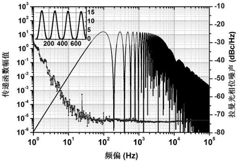
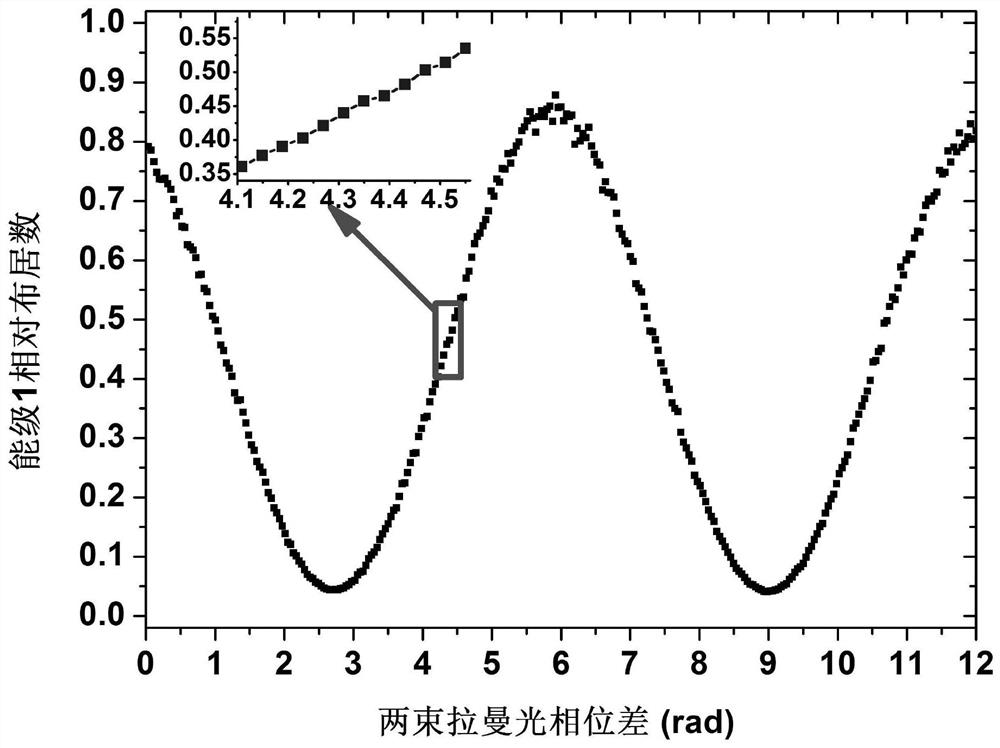
[0035] Such as Figure 1~4 As shown, this embodiment provides a Raman optical phase noise testing method based on cold atom interference, including the following steps:

[0036] Step 1, turn on the cooling light and back-pumping light, turn on the gradient magnetic field, realize atom trapping and cooling, and obtain cold atomic clusters;

[0037] Step 2: Use stimulated Raman transition or microwave state selection to realize the preparation of the initial state of the cold atomic group to a predetermined atomic energy level; the specific atomic energy level can be set according to different atomic types;

[0038] In step 3, the cold atomic clusters are freely falling or projected into the interference area. During this process, the cold atomic clusters and the pulse width are respectively pulse, π pulse, Pulsed Raman light interacts three times to achieve atomic interference;

[0039] Step 4, performing dual-level detection on the interfering atoms in the detection area ...

Embodiment 2

[0101] Such as Figure 4 As shown, on the basis of Embodiment 1, this embodiment provides a Raman optical phase noise test system based on cold atom interference, which includes in the vertical direction:

[0102] Atom cooling area, including gradient magnetic field coils, cooling light and back-pumping light input devices, cooling cavity under vacuum environment, to trap and cool atomic groups;

[0103] The interference area includes a vertical channel directly below or directly above the atomic cooling area, and the interior of the vertical channel is connected to the cooling cavity, which is used to provide a place for atomic groups to interact with Raman light to achieve atomic interference;

[0104] The detection area includes an atomic double-level detection device, including a horizontal detection light facing the atomic group at the bottom of the vertical channel, a beam expander for back-pumping light, and a photoelectric receiving device for receiving the fluorescent...


PUM


Abstract

The invention discloses a Raman light phase noise testing method and system based on cold atom interference, and the method comprises the steps: carrying out the atom trapping and cooling, and obtaining a cold atom group; preparing an atom initial state; enabling the cold atomic group to enter an interference area, and controlling an experiment time sequence to achieve atomic interference throughinteraction of three Raman light pulses and the cold atomic group; enabling atomic groups to enter a detection area for double-energy-level detection to obtain atomic interference fringes; setting a phase difference between the two beams of Raman pulses, and enabling the relative population to be placed at a stripe half-width position to obtain stripe phase jitter; deducting contribution of Ramanlight power noise, quantum projection noise and technical noise to obtain influence of Raman light relative to phase noise; changing the free evolution time of atoms in the interference process, repeating the steps, and solving an equation set according to the Leeson model and transfer functions under different experiment time sequences to obtain the Raman light phase noise spectrum. The problem that periodic calibration is needed in an existing phase noise measurement technology is solved, the test accuracy is improved, and a self-calibration function is provided.

Description

technical field [0001] The invention relates to the technical field of noise testing, in particular to a Raman optical phase noise testing method and system based on cold atom interference. Background technique [0002] In the field of quantum precision measurement based on atomic interference technology such as atomic clocks and gravimeters, the phase noise of the local oscillator is an important noise source that affects the test sensitivity. During the operation of the atomic clock, the phase noise of the local oscillator will deteriorate the frequency stability of the atomic clock (Dick effect); in the cold atom interferometer, the phase noise of the Raman light will also cause the phase jitter of the interference fringes, thereby reducing the system test sensitivity. [0003] The above-mentioned effects of the phase noise of the local oscillator and Raman light are essentially caused by the sensitive response of the transition probability of cold atoms to phase noise, ...

Claims


Application Information

Patent Timeline
Patent Type & Authority Applications(China)
IPC IPC(8): G01J9/02
CPCG01J9/02G01J2009/0238
Inventor 王亚宁杨俊颜树华朱凌晓王国超贾爱爱李期学张旭
Owner NAT UNIV OF DEFENSE TECH
Why Eureka
Try Eureka