A gas phase aldehyde hydrogenation reactor

A hydrogenation reactor and gas-phase aldehyde technology, applied in chemical instruments and methods, chemical/physical processes, etc., can solve problems such as easy damage, catalyst damage and crushing, catalyst consumption, etc., to improve reaction rate, reduce investment cost, The effect of saving the amount of loading

Active Publication Date: 2021-03-16
NINGBO JUHUA CHEM TECH CO LTD
View PDF5 Cites 0 Cited by
  • Summary
  • Abstract
  • Description
  • Claims
  • Application Information

AI Technical Summary

Problems solved by technology

[0004] At present, in the existing gas-phase aldehyde hydrogenation reaction, multiple catalyst beds are installed inside the reactor to realize the reaction of the mixed gas and hydrogen. However, during the gas-phase aldehyde hydrogenation reaction, the catalyst bed will continue to The catalyst on the layer reacts, which will easily lead to the continuous consumption of the catalyst, and the main factors that lead to the consumption of the catalyst are the following factors:
[0005] 1. During the reaction of gas-phase aldehyde in the reactor, the gas-phase aldehyde introduced contains oxygen. During the heating reaction in the reactor, it is easy to generate oxides and precipitate and adhere to the catalyst bed, or even cover the catalyst. , causing the catalyst to fail to react;
[0006] 2. During the reaction process at the corners and water chestnuts of the catalytic bed, the granular catalyst is prone to damage after a long time. If the catalyst is not replaced in time, the catalyst will be damaged and pulverized, and the fine powder of the catalyst will be deposited on the Catalyst bed, causing reactor pressure drop problems;
[0007] However, because the reactor is relatively sealed, it is difficult to load and replace the catalyst, which affects the overall reaction efficiency of the reactor. Therefore, we propose a gas-phase aldehyde hydrogenation reactor

Method used


Image

  • A gas phase aldehyde hydrogenation reactor
  • A gas phase aldehyde hydrogenation reactor
  • A gas phase aldehyde hydrogenation reactor

Examples


Embodiment Construction

[0030] The following will clearly and completely describe the technical solutions in the embodiments of the present invention with reference to the accompanying drawings in the embodiments of the present invention. Obviously, the described embodiments are only some, not all, embodiments of the present invention. Based on the embodiments of the present invention, all other embodiments obtained by persons of ordinary skill in the art without making creative efforts belong to the protection scope of the present invention.

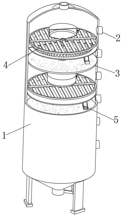
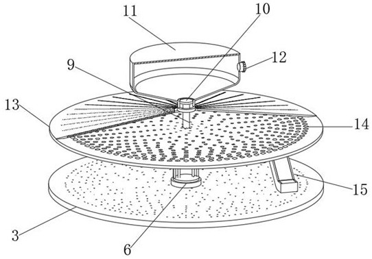
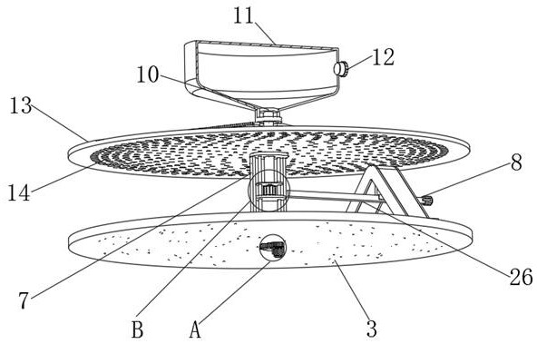
[0031] see Figure 1-8 , the present invention provides a technical solution: a gas-phase aldehyde hydrogenation reactor, comprising a reactor body 1, a manhole 2 arranged on the reactor body 1, a catalyst bed body 3 arranged inside the reactor body 1, and There are several holes 2, and several distributors 4 are manually distributed on the outside of several catalyst bed bodies 3 and distributed on the catalyst bed bodies 3;

[0032] The catalyst bed body 3 ...


PUM


Abstract

The invention discloses a gas-phase aldehyde hydrogenation reactor, which comprises a reactor body, a manhole arranged on the reactor body, a catalyst bed body arranged inside the reactor body, and a distributor distributed on the catalyst bed body. The catalyst bed is provided with a driving loading device that is convenient for catalyst replacement and loading. This gas-phase aldehyde hydrogenation reactor is provided with a catalyst loading device on the corresponding catalyst body inside the reactor body. The catalyst loading device can make The catalyst is evenly distributed on the catalyst bed, and the loaded catalyst can be evenly paved and compacted. At the same time, after the catalyst has reacted many times, the reacted catalyst can be unloaded in time. It can not only ensure the complete unloading, but also save the amount of catalyst loading as much as possible, reduce the primary investment cost, and thus effectively improve the reaction rate of gas phase aldehydes.

Description

technical field [0001] The invention relates to the technical field of hydrogenation reactors, in particular to a gas-phase aldehyde hydrogenation reactor. Background technique [0002] The hydrogenation reactor is a very important piece of equipment in the organic chemistry laboratory and the actual production process. It can not only be used as a hydrogenation reaction container, but also in occasions where liquid and gas need to be fully mixed. [0003] The gas phase aldehyde enters the inside of the reaction tower body through the feed inlet at the top of the tower body, and the addition of cold and hot hydrogen is automatically controlled by the multi-level adjustment system of the reaction tower body, so that the hydrogen gas is directly passed into the catalytic bed layer to play a role in reacting with the gas phase aldehyde. The mixed gas reacts, and finally liquid alcohol is obtained and flows out through the outlet at the bottom of the reactor. [0004] At presen...

Claims


Application Information

Patent Timeline
Patent Type & Authority Patents(China)
IPC IPC(8): B01J8/02
CPCB01J8/02B01J8/0015
Inventor 周强钟骏良李刚涂齐辉杜继立吴刚徐云雁吴丹平徐翔
Owner NINGBO JUHUA CHEM TECH CO LTD
Why Eureka
Try Eureka