Aluminum pot processing device for kitchen ware processing

A technology of processing device and aluminum pan, which is applied in spraying device, liquid spraying device and other directions, can solve the problems of labor-consuming, cumbersome operation process, affecting the use effect, etc., and achieve the effect of saving labor and simple operation.

Active Publication Date: 2020-11-13
永康市翁氏科技有限公司
View PDF6 Cites 2 Cited by
  • Summary
  • Abstract
  • Description
  • Claims
  • Application Information

AI Technical Summary

Problems solved by technology

[0006] In order to overcome the disadvantages that the operation process of the above-mentioned method is cumbersome and labor-intensive, and manual operation cannot evenly scrape the graphite powder liquid on the outer surface of the aluminum pot, which easily affects the subsequent use effect, the technical problem to be solved by the present invention is to provide An aluminum pot processing device for kitchenware processing that is simple to operate, can save manpower, and can evenly scrape graphite powder liquid on the outer surface of the aluminum pot

Method used


Image

  • Aluminum pot processing device for kitchen ware processing
  • Aluminum pot processing device for kitchen ware processing
  • Aluminum pot processing device for kitchen ware processing

Examples


Embodiment 1

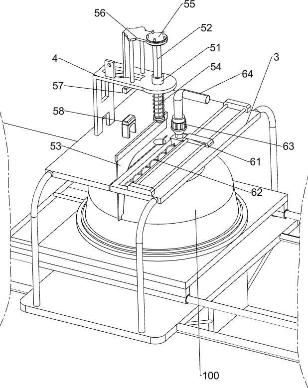
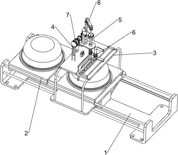
[0023] A kind of aluminum pan processing device for processing kitchen utensils, such as Figure 1-2 As shown, it includes a mounting base 1, a placement plate 2, a mounting plate 3 and a mounting frame 4. The mounting base 1 is slidably connected with a placement plate 2, the middle part of the mounting base 1 is connected with a mounting plate 3, and the left side of the mounting plate 3 is connected with a The mounting frame 4 also includes a lifting assembly 5 and a blanking assembly 6 , the lifting assembly 5 is provided between the mounting frame 4 and the mounting plate 3 , and the blanking assembly 6 is provided on the mounting plate 3 .

[0024] The lifting assembly 5 includes an inner diamond sleeve 51, a rhombus rod 52, a scraper 53, a tension spring 54, a connecting sleeve 55, a sliding frame 56, an iron block 57 and an electromagnet 58, and the mounting frame 4 is rotatably connected with an internal The diamond-shaped sleeve 51 is slidingly connected with a rhomb...

Embodiment 2

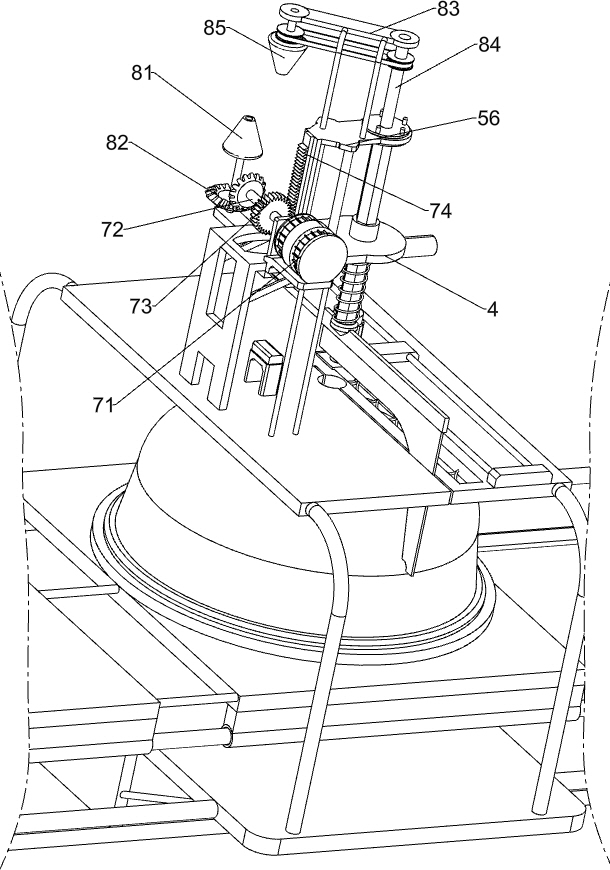
[0028] On the basis of Example 1, such as image 3 As shown, drive assembly 7 is also included. Drive assembly 7 includes servo motor 71, rotating shaft 72, drive gear 73 and drive rack 74. Servo motor 71 is installed on the left side of the top of mounting frame 4. On the output shaft of servo motor 71 A rotating shaft 72 is connected, a driving gear 73 is connected on the rotating shaft 72 , a driving rack 74 is connected on the sliding frame 56 , and the driving gear 73 is meshed with the driving rack 74 .

[0029] When it is necessary to pull the rhombic rod 52 to move downward, the servo motor 71 can be started to drive the rotating shaft 72 to rotate, the rotating shaft 72 rotates to drive the driving gear 73 to rotate, the driving gear 73 rotates and pokes the driving rack 74 to move downward, and the driving rack 74 moves downward The movement drives the sliding frame 56 to move downward, the sliding frame 56 moves downward to drive the connecting sleeve 55 to move dow...


PUM


Abstract

The invention relates to a processing device, and particularly relates to an aluminum pot processing device for kitchen ware processing. The aluminum pot processing device for kitchen ware processingis easy to operate, capable of saving manpower and capable of evenly scraping graphite powder liquid on the outer surface of an aluminum pot. The aluminum pot processing device for kitchen ware processing comprises an installation base, an installation plate, a lifting assembly and a discharging assembly, wherein a containing plate is connected to the installation base in a sliding mode; the installation plate is connected to the middle of the installation base; an installation frame is connected to one side of the installation plate; the lifting assembly is arranged between the installation frame and the installation plate; and the discharging assembly is arranged on the installation plate. According to the aluminum pot processing device for kitchen ware processing, the lifting assembly and the discharging assembly are matched to operate to process the aluminum pot, and therefore the effect of processing the aluminum pot is achieved.

Description

technical field [0001] The invention relates to a processing device, in particular to an aluminum pot processing device for processing kitchen utensils. Background technique [0002] The aluminum pot is light, durable, fast heating, even heat conduction, and no rust. It is understood that aluminum products mainly include refined aluminum (soft aluminum) products and cast aluminum (hard aluminum) products, and the materials are aluminum and aluminum alloy. The surface color can be divided into white, light yellow and other colors. White aluminum products are divided into two types: casting and stamping. After the aluminum pot is made, it is usually coated with a layer of graphite powder on its outer surface so that the aluminum water does not stick to the mold. [0003] At present, the way to smear graphite powder on the outer surface of the aluminum pot is usually to pour the graphite powder on the aluminum pot first, and then manually operate the scraper to scrape the gr...

Claims


Application Information

Patent Timeline
Patent Type & Authority Applications(China)
IPC IPC(8): B05B9/04B05B13/02B05B15/00B05B15/68
CPCB05B9/0403B05B13/0285B05B15/00B05B15/68
Inventor 龚莉莉
Owner 永康市翁氏科技有限公司
Why Eureka
Try Eureka