Directional solidification device and casting method

A technology of directional solidification and lifting device, which is applied in the field of precision casting, can solve the problems of freckles in single crystal blade casting process, and achieve the effect of eliminating freckle defects and avoiding convection phenomenon

Inactive Publication Date: 2020-11-13
深圳市万泽中南研究院有限公司 +1
View PDF5 Cites 4 Cited by
  • Summary
  • Abstract
  • Description
  • Claims
  • Application Information

AI Technical Summary

Problems solved by technology

[0005] The purpose of the present invention is to solve the problem of freckles in superalloy orientation and single crystal blade casting process

Method used


Image

  • Directional solidification device and casting method
  • Directional solidification device and casting method

Examples


Embodiment 1

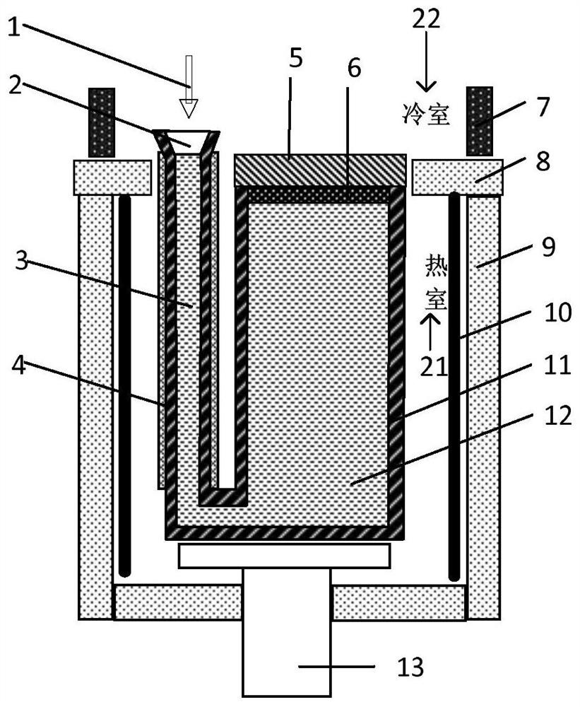
[0025] like figure 1 and figure 2 As shown, the present invention provides a kind of directional solidification device, and described device comprises: hot room 21 and cold room 22, and described cold room 22 is arranged on the top of described hot room 21, and described hot room 21 and cold room 22 A heat insulating board 8 is provided between them.

[0026] Wherein, a heater 10, a lifting device 13, and a mold shell 11 are arranged in the hot chamber 21, a cooling ring 7 is arranged in the cold chamber 22, and the heater 10 is arranged around the mold shell 11; The upper part of the mold case 11 is open, and a cooling plate 5 is arranged at the opening for sealing.

[0027] In this embodiment, the runner of the mold shell 11 is a sprue 3 , and the sprue 3 is arranged on one side of the mold shell 11 and communicates with the cavity 12 of the mold shell 11 at the bottom. The sprue wrapped by the insulation material forms a liquid pressure head with a certain height differ...

Embodiment 2

[0036] The present invention also provides a method for directional solidification casting based on the directional solidification device described in Embodiment 1, refer to figure 1 and figure 2 , which includes the steps:

[0037] S1, placing the formwork 11 in the heat chamber 21 for preheating;

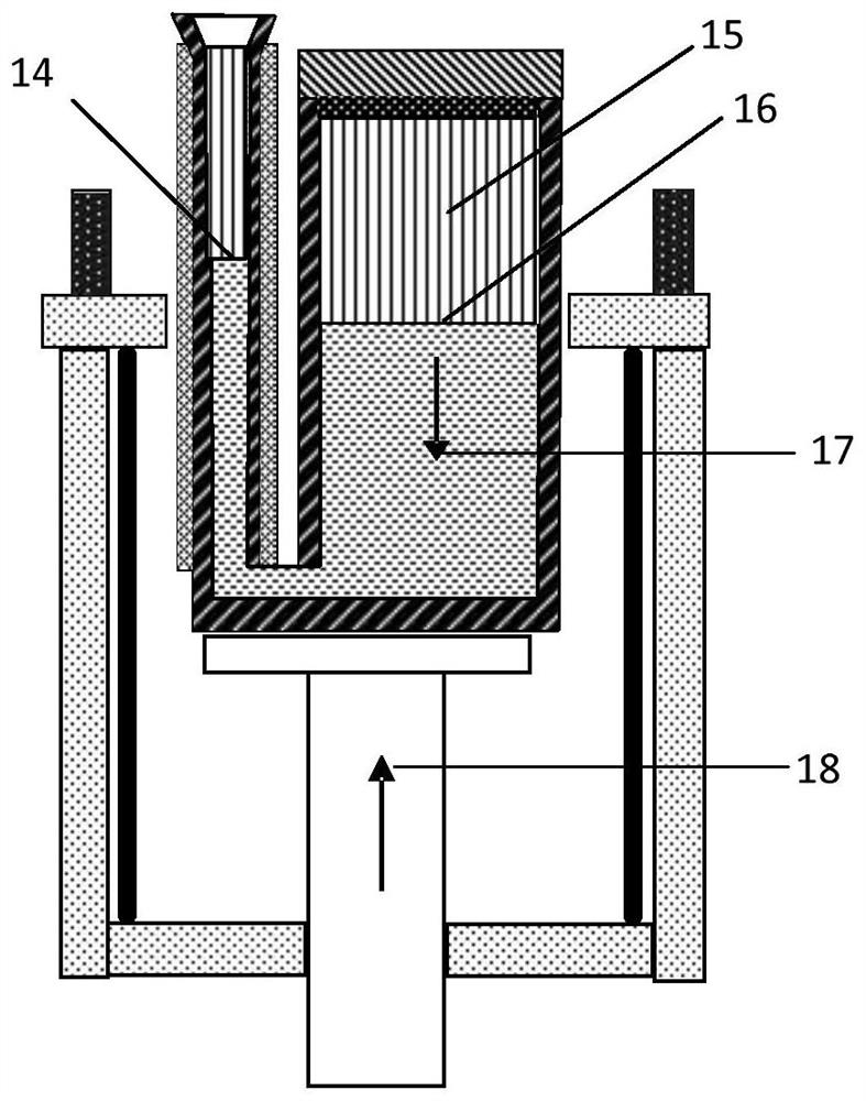
[0038] S2, pour the alloy liquid through the gate 2 of the mold shell 11 along the direction of gravity 1, so that the alloy liquid enters the cavity 12 through the sprue 3, rises to the top opening and contacts the cooling plate 5 to form a cooling layer 6;

[0039] S3, after the pouring is completed, the mold shell 11 after pouring is passed through the heat insulating plate 8 by the hot chamber 21 to the cold chamber 22 at a predetermined speed through the lifting device 13 along the upward direction 18, and the rising speed is controlled at 1 to 10 mm / min. During the rising process of the mold shell, the molten metal in the mold shell gradually solidifies downward from the...


PUM


Abstract

The invention discloses a directional solidification device and a casting method. The device comprises a hot chamber and a cold chamber, the cold chamber is arranged above the hot chamber, a heat insulation plate is arranged between the hot chamber and the cold chamber, a heater, a lifting device and a mold shell are arranged in the hot chamber, a cooling ring is arranged in the cold chamber, theheater is arranged around the mold shell, an opening is formed in the upper part of the mold shell, and a chilling plate is arranged at the opening. Compared with a traditional mode, the solidification direction is changed into the clockwise gravity direction from the anticlockwise gravity direction, so that liquid in the pasty area is in a stable state with the light upper portion and the heavy lower portion, the convection phenomenon caused by anticlockwise gravity solidification in the traditional technology is avoided, and the freckle defect commonly existing in high-temperature alloy orientation and single crystal castings is eliminated from the source.

Description

technical field [0001] The invention relates to precision casting technology, and more specifically relates to a directional solidification device and a casting method. Background technique [0002] Aeroengines and gas turbines are the most high-end products of modern manufacturing, and the directional and single-crystal blades made of superalloys are the most important core hot-end components. Since the 1970s, Bridgman-type directional solidification furnaces have been used in the world to produce directional and single crystal blades. The structural feature of the furnace is that it is divided into upper and lower chambers. The upper chamber is composed of a melting crucible and a mold shell heating chamber, and the lower chamber is a cooling chamber. [0003] When the Bridgman furnace is working, first preheat the ceramic formwork in the heating chamber, pour the molten alloy liquid, then lower the formwork, pass through the heat shield from the heating area and enter th...

Claims


Application Information

Patent Timeline
Patent Type & Authority Applications(China)
IPC IPC(8): B22D27/04C30B29/52C30B11/00
CPCB22D27/045C30B11/00C30B29/52
Inventor 马德新崔树森徐维台
Owner 深圳市万泽中南研究院有限公司
Why Eureka
Try Eureka