A sander loading machine convenient for quantitative output

A technology of sanding machine and material machine, which is applied in the direction of grinding frame, grinding machine parts, grinding/polishing equipment, etc. It can solve the problems of calculation of the quantity of materials that cannot be transported, fatigue and errors, etc.

Active Publication Date: 2021-07-20
盐城鼎恒机械有限公司
View PDF8 Cites 0 Cited by
  • Summary
  • Abstract
  • Description
  • Claims
  • Application Information

AI Technical Summary

Problems solved by technology

[0005] The purpose of the present invention is to solve the problem existing in the prior art that when placing the material on the lifting platform, the quantity of the material transported each time cannot be calculated, and manual calculation is easy to cause fatigue in the prior art. And the shortcomings of error, and proposed a sanding machine feeding machine that is convenient for quantitative output

Method used

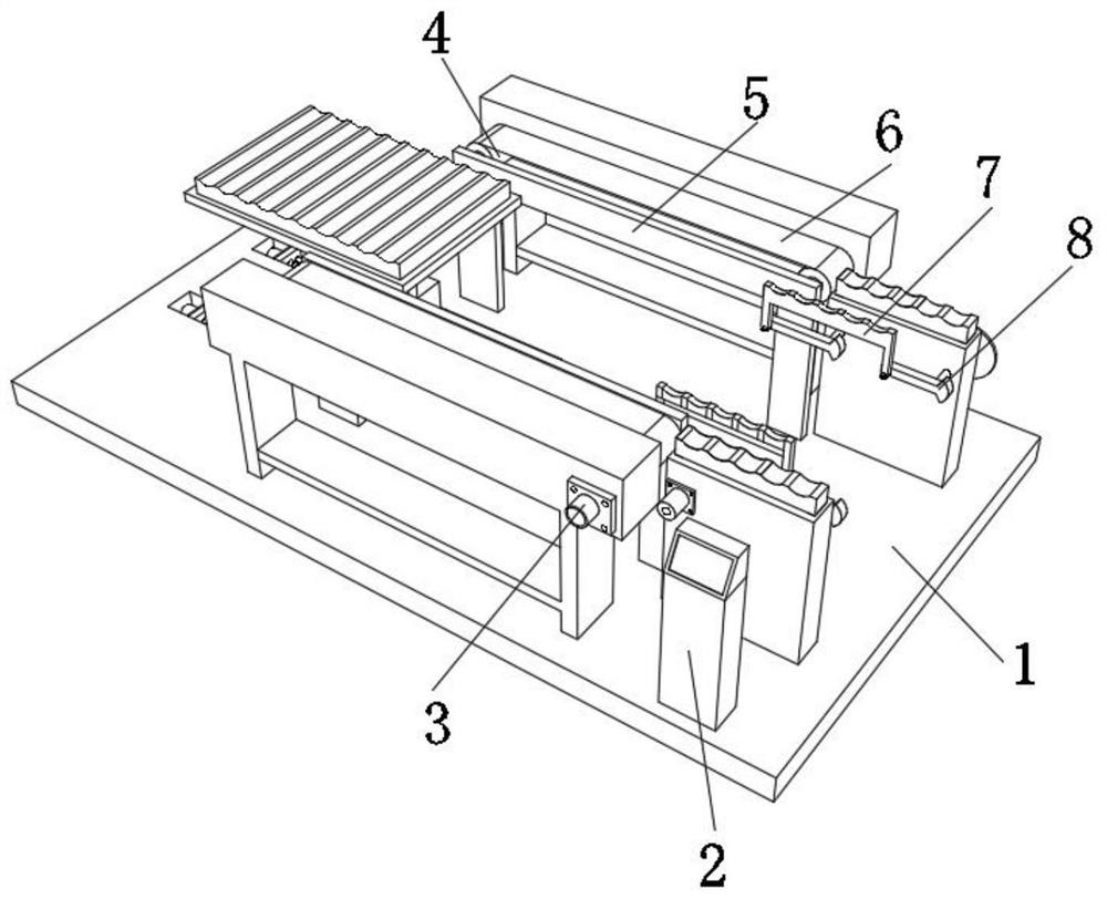
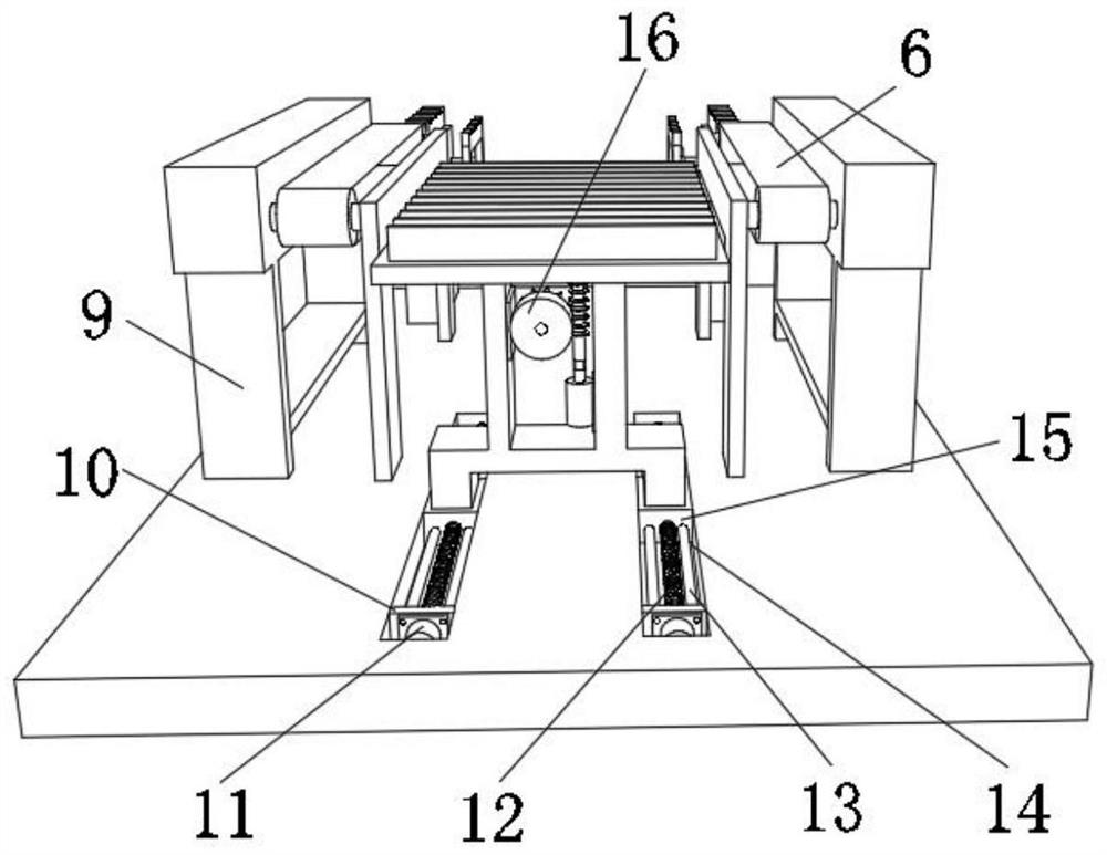
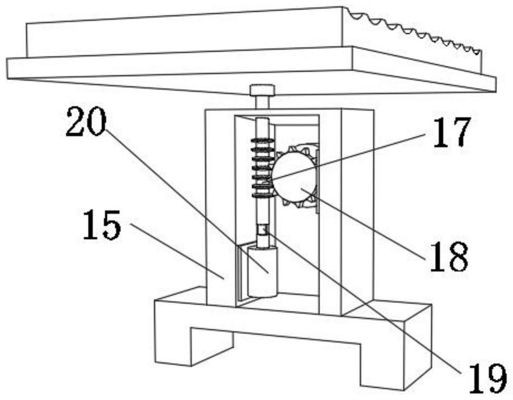

Image

  • A sander loading machine convenient for quantitative output
  • A sander loading machine convenient for quantitative output
  • A sander loading machine convenient for quantitative output

Examples


Embodiment Construction

[0028] The technical solution of this patent will be further described in detail below in conjunction with specific embodiments.

[0029] Embodiments of the present patent are described in detail below, examples of which are shown in the drawings, wherein the same or similar reference numerals designate the same or similar elements or elements having the same or similar functions throughout. The embodiments described below by referring to the figures are exemplary and are only used for explaining the patent, and should not be construed as limiting the patent.

[0030] In the description of this patent, it is to be understood that the terms "center", "upper", "lower", "front", "rear", "left", "right", "vertical", "horizontal", The orientation or positional relationship indicated by "top", "bottom", "inner", "outer", etc. is based on the orientation or positional relationship shown in the drawings, and is only for the convenience of describing this patent and simplifying the des...


PUM


Abstract

The invention discloses a sander feeding machine which is convenient for quantitative output, and relates to the technical field of sander feeding machines; in order to carry out quantitative output of materials; it specifically includes a base, and the outer wall of the top of the base is welded with two mounting plates, one of which is The outer wall of one side of the mounting plate is rotatably connected with a rotating shaft, the outer wall of the circumference of the rotating shaft is welded with a rotating disc, the outer wall of the top of the rotating disc is welded with a moving column, and the outer wall of one side of the mounting plate is rotatably connected with an intermittent motion disc through the rotating shaft. Four accommodating grooves are provided on the outer wall around the intermittent motion disc, and the outer peripheral wall of the moving column is slidably connected to the inner wall of the accommodating groove, and the outer wall of the rotating shaft of the intermittent motion disc is welded with a second transmission roller. In the present invention, two rotating rods and a placing frame are arranged on the inner wall of one side of the same mounting plate to form a transmission mechanism, and the rotation of the two rotating rods can be used to realize the effect of transferring the material on the top of the discharging frame through the placing frame.

Description

technical field [0001] The invention relates to the technical field of sander loaders, in particular to a sander loader which is convenient for quantitative output. Background technique [0002] Sanding machine is a machine for polishing and polishing the surface of wood and other items. Its function is to make the surface of the material smoother. During the sanding process of the sanding machine, it is necessary to load the sanding machine through the feeding machine, but The current feeding machine can only play the role of feeding, and cannot quantitatively output the amount of feeding, and cannot calculate the number of feeding. [0003] After searching, the Chinese patent application number is 201620373160.5, which discloses a sander feeding device, including a sander and a feeding device, characterized in that: the sander includes a feeding conveyor belt, materials, coarse sand Roller, Coarse Belt Tension Roller, Coarse Belt, Front Platen, Middle Platen, Fine Sand Ro...

Claims


Application Information

Patent Timeline
Patent Type & Authority Patents(China)
IPC IPC(8): B24B41/00B24B41/02B24B49/12
CPCB24B41/005B24B41/02B24B49/12
Inventor 李青祝马玉娟李清华张培培
Owner 盐城鼎恒机械有限公司
Why Eureka
Try Eureka