Flexographic printing equipment
A kind of equipment and flexo printing technology, applied in printing, printing machines, rotary printing machines, etc., can solve the problems of low production efficiency, achieve the effects of improved production efficiency, good drying effect, and simplified production
- Summary
- Abstract
- Description
- Claims
- Application Information
AI Technical Summary
Problems solved by technology
Method used
Image
Examples
Embodiment 1
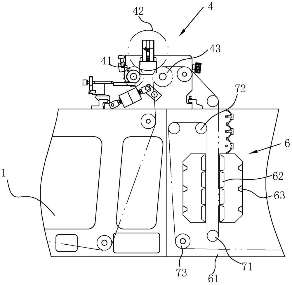
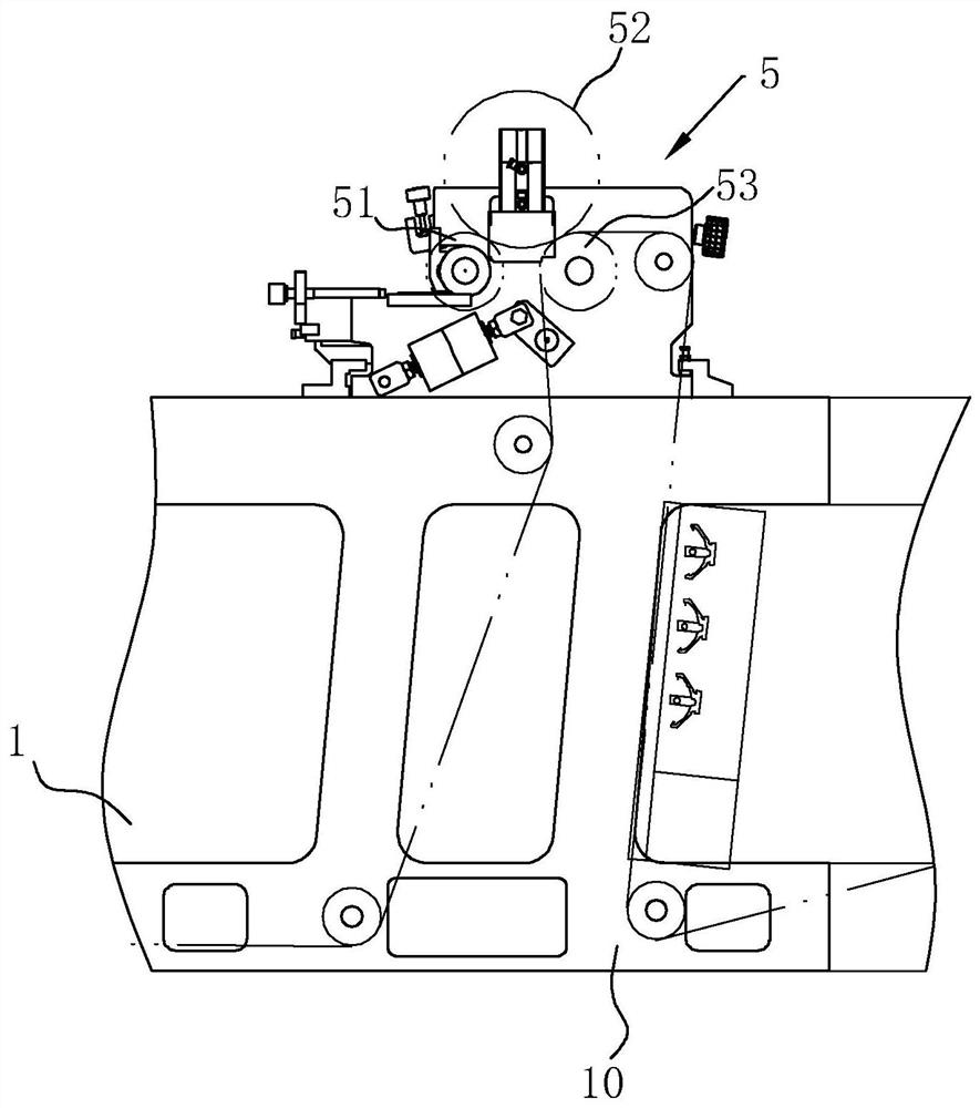
[0043] refer to figure 1, a kind of flexo printing equipment includes a strip-shaped body 1, and an unwinding mechanism 2 is arranged at the head end of the body 1, a winding mechanism 3 is arranged at the end of the body 1, and a winding mechanism 3 is arranged in the middle of the body 1 along the conveying direction Coating mechanism 4, drying mechanism 6 and printing mechanism 5, wherein coating mechanism 4 is used for coating degradable plastic layer; Wherein unwinding mechanism 2 comprises the unwinding roller 21 that is rotatably connected on the body 1, and rewinding mechanism 3 comprises rotatably connected The winding roller 31 on the body 1, and the drive motor (not shown in the figure) that drives the winding roller 31 to rotate is arranged on the body 1, so that the winding and unwinding can be realized by the rotation of the winding roller 31 The roller 21 is continuously discharging, and the paper tape passes through the coating mechanism 4, the drying mechanism...
Embodiment 2
[0051] refer to Figure 4 , a kind of flexo printing equipment, its main difference from Embodiment 1 lies in the difference of the drying mechanism 6, in this embodiment, the second pulling roller 72 is located on the top outside the box body 61, and the third pulling roller 73 is located on the top outside the box body 61 At the bottom, the middle part of the box body 61 is provided with a partition 67 to form an upper chamber 65 and a lower chamber 66. The first traction roller 71 is located in the upper chamber 65, and the partition 67 is provided with a perforation 68, and the infrared heating tube 62 is arranged on the upper chamber. On the opposite inner wall of the cavity 65; on the opposite side wall of the box body 61 corresponding to the lower cavity 66, there is a slot 69 for the paper tape to pass through, so that the paper tape penetrates into the box body 61 and first passes through the upper cavity 65 to achieve the first drying and curing , then pass through t...
Embodiment 3
[0053] Such as Figure 5 As shown, a flexographic printing equipment differs from Embodiment 1 in that the traction mechanism includes a fourth traction roller 81 and a fifth traction roller 82, and the fourth traction roller 81 and the fifth traction roller 82 are both Rotationally connected on the machine body 1, the fourth traction roller 81 is positioned obliquely above the coating roller 42, that is, the fourth traction roller 81 is higher than the coating roller 42, and the fifth traction roller 82 is arranged at the bottom of the corresponding body 1, so that after coating The paper tape of the cover roller 42 will be continuously conveyed obliquely for a certain distance, and the machine body 1 is also provided with a drying mechanism 6 at the corresponding distance. The drying mechanism 6 includes an infrared heating tube 62 and is located near the paper tape coated with a degradable plastic layer. On one side of the degradable plastic layer, the degradable plastic la...
PUM
 Abstract
Description
Claims
Application Information
 - R&D
- Intellectual Property
- Life Sciences
- Materials
- Tech Scout
- Unparalleled Data Quality
- Higher Quality Content
- 60% Fewer Hallucinations
Browse by: Latest US Patents, China's latest patents, Technical Efficacy Thesaurus, Application Domain, Technology Topic, Popular Technical Reports.
© 2025 PatSnap. All rights reserved.Legal|Privacy policy|Modern Slavery Act Transparency Statement|Sitemap|About US| Contact US: help@patsnap.com


