Lifting device for repairing numerically-controlled machine tool

A technology of lifting device and CNC machine tool, which is applied in the direction of lifting device, lifting frame, lifting equipment safety device, etc., can solve the problems of low safety and injury of maintenance personnel, achieve high safety, prevent sudden fall, and improve stability Effect

Inactive Publication Date: 2020-11-13
扬州华交轨道交通科技有限公司
View PDF8 Cites 4 Cited by
  • Summary
  • Abstract
  • Description
  • Claims
  • Application Information

AI Technical Summary

Problems solved by technology

[0004] In order to overcome the problems of low safety and easy injury to maintenance personnel in the prior art, the present invention provides a lifting device for maintenance of CNC machine tools, which includes two moving plates, and four symmetrical fixed mountings on the top of the moving plates. a support rod distributed in a rectangular shape, the top of the four support rods is fixedly mounted with the same support plate, the top of the support plate is fixedly mounted with a motor frame, the top of the motor frame is fixedly mounted with a motor, the moving plate and The same lifting rod is installed in rotation between the support plates, the top of the lifting rod is fixedly connected with the output shaft of the motor, the outer fixing sleeve of the lifting rod is provided with a threaded pipe, and the outer side of the threaded pipe is fixed A lifting plate that is slidably connected to the four support rods is set, and a lifting plate is fixedly installed on the sides of the two lifting plates that are close to each other. The lifting plate is provided with four rectangularly distributed anti-falling mechanisms. , the anti-falling mechanism is connected with the support rod, and the sides of the two lifting plates away from each other are provided with counterweights fixedly installed on the top of the corresponding moving plate

Method used


Image

  • Lifting device for repairing numerically-controlled machine tool
  • Lifting device for repairing numerically-controlled machine tool
  • Lifting device for repairing numerically-controlled machine tool

Examples


Embodiment Construction

[0022] The present invention will be described in further detail below in conjunction with the accompanying drawings and embodiments. It should be understood that the specific embodiments described here are only used to explain the present invention, not to limit the present invention.

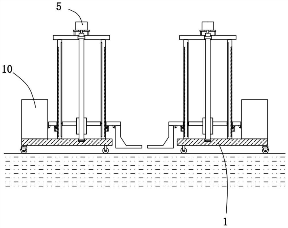
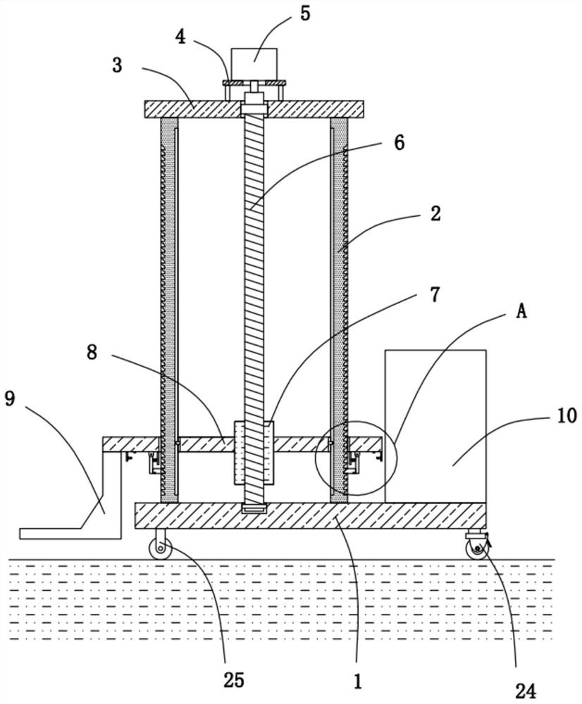
[0023] Please refer to Figure 1-5 , the present invention provides a technical solution: a lifting device for CNC machine tool maintenance, including two moving plates 1, four support rods 2 distributed in a rectangular shape are symmetrically fixed on the top of the moving plates 1, and the four The top of the support bar 2 is fixedly installed with the same support plate 3, the top of the support plate 3 is fixedly equipped with a motor frame 4, and the top of the motor frame 4 is fixedly installed with a motor 5, the moving plate 1 and the support plate 3 The same elevating rod 6 is installed in rotation, the top of the elevating rod 6 is fixedly connected with the output shaft of the mot...


PUM


Abstract

The invention provides a lifting device for repairing a numerically-controlled machine tool. The lifting device comprises two movable plates; four support rods in rectangular distribution are symmetrically and fixedly mounted on the tops of the movable plates; the same support plate is fixedly mounted at the top ends of the four support rods; a motor frame is fixedly mounted on the top of the support plate; a motor is fixedly mounted on the top of the motor frame; the same lifting rod is rotatably mounted among the movable plates and the support plate; the top end of the lifting rod is fixedlyconnected with the output shaft of the motor; a threaded pipe is fixedly arranged on the outer side of the lifting rod in a sleeving manner; two lifting plates in sliding fit with the four support rods fixedly sleeve the outer side of the threaded pipe; and elevating plates are fixedly mounted on two mutually closed sides of the two lifting plates. The lifting device is convenient to use and highin stability and safety and can prevent a risen numerically-controlled machine tool from falling off suddenly while lifting the numerically-controlled machine tool.

Description

technical field [0001] The invention relates to the technical field of maintenance of numerical control machine tools, in particular to a lifting device for maintenance of numerical control machine tools. Background technique [0002] CNC machine tool is the abbreviation of numerical control machine tool, which is an automatic machine tool equipped with a program control system. The control system can logically process programs with control codes or other symbolic instructions, decode them, express them in coded numbers, and input them into the numerical control device through the information carrier. After calculation and processing, various control signals are sent by the numerical control device to control the movement of the machine tool, and the parts are automatically processed according to the shape and size required by the drawing. [0003] After retrieval, the application number is: 201820620745.1 A lifting device for CNC machine tool maintenance disclosed, includi...

Claims


Application Information

Patent Timeline
Patent Type & Authority Applications(China)
IPC IPC(8): B66F7/00B66F7/28B66F17/00
CPCB66F7/025B66F7/28B66F17/006
Inventor 金传辉金菘乔翔宇陈坚
Owner 扬州华交轨道交通科技有限公司
Why Eureka
Try Eureka