
Impactor air distribution device and matched impactor

A technology of impactor and gas distribution, which is applied to the driving device for drilling in the borehole, drilling equipment, earthwork drilling and production, etc. It can solve the problems of insufficient impact energy, high cost of reserve impactors, and large waste of impact energy.

Active Publication Date: 2020-11-13
长沙天和钻具机械有限公司
View PDF6 Cites 0 Cited by
  • Summary
  • Abstract
  • Description
  • Claims
  • Application Information

AI Technical Summary

Problems solved by technology

[0002] The drilling operation of the down-the-hole drilling system is an efficient and high-quality hole-forming operation technology commonly used in the surface drilling and blasting, water well, geothermal and deep well drilling industries. However, the conventional drilling tools used in the down-the-hole drilling system often have to face The depth, cover layer thickness, and rock hardness are different in the working environment, and the performance parameters required by different working environments are different. Therefore, when using an impactor to deal with it, when the hole is not deep or the rock is not hard The waste of impact energy is large; when the hole is deep and the rock is hard, the gas volume is insufficient and the impact energy is not enough
The currently implemented measures are to store impactors with different air consumption and different impact energy to deal with this situation. Although this solution can rarely meet the requirements of the construction method, the cost of the required reserve impactors is too high, especially in the face of different construction site, and it is more obvious when the distance is far

Method used


Image

  • Impactor air distribution device and matched impactor
  • Impactor air distribution device and matched impactor
  • Impactor air distribution device and matched impactor

Examples


Embodiment 1

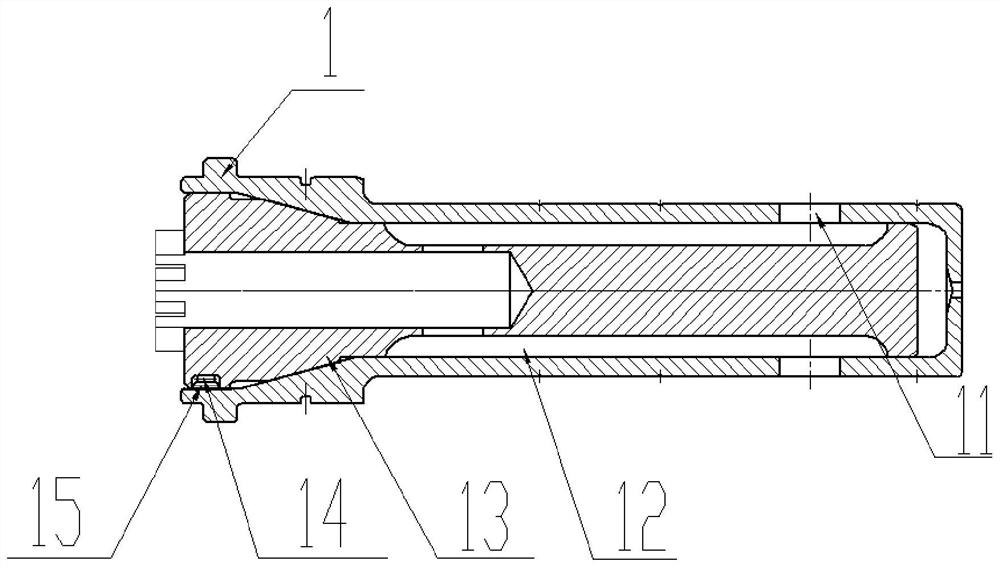
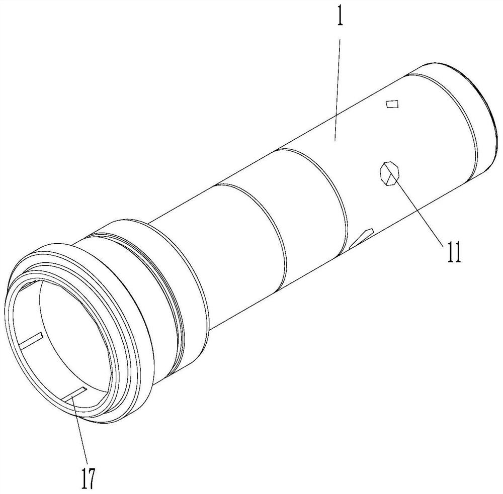
[0025] Such as figure 2 , 3 , 4, a gas distribution device for an impactor, including a gas distribution rod 1 installed in the impactor, the middle part of the gas distribution rod 1 is provided with a cavity that matches the size of the gas distribution rod core 13, the gas distribution rod 1 The gas rod core 13 is coaxially sealed and installed in the cavity of the gas distribution rod 1. The middle part of the gas distribution rod core 13 is arranged with an air inlet channel along the axial direction, and the outer wall of the gas distribution rod core 13 is provided with multiple sets of The gas distribution and air groove groups arranged in the direction, each group of gas distribution and gas groove groups include two gas distribution and gas grooves 12, and the gas distribution and gas grooves 12 are symmetrically arranged around the central axis of the gas distribution rod core 13. An air distribution air channel is formed between the air groove 12 and the inner wa...

Embodiment 2

[0030] Embodiment 2: As an application of the gas distribution device of the impactor of the device:

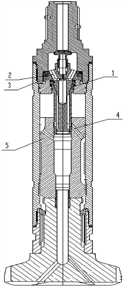
[0031] Such as figure 1 As shown, it includes an impactor, the impactor includes the impactor gas distribution device in Embodiment 1, and the impactor gas distribution device is installed between the check valve seat 3 and the piston 5 of the impactor. The air distribution device of the impactor is provided with clamping parts, and the outer cylinder of the impactor is provided with a plurality of card slots matching with the clamping parts. In the outer cylinder of the impactor, and axially positioned in the outer cylinder through the impactor joint installed on the outer cylinder of the impactor, the air channel 2 of the check valve seat communicates with the air distribution channel through the air intake channel of the valve rod core 13, the said The gas distribution rod 1 is inserted in the intake passage of the piston 5 .

[0032] The configuration process of the spe...

Embodiment 3

[0035] The application of specific examples is as follows:

[0036] Three sets of air distribution holes are set on the air distribution rod 1, the position of the first set of air distribution holes makes the maximum stroke of the piston 73mm, the position of the second set of air distribution holes makes the maximum stroke of the piston 82mm, and the position of the third set of air distribution holes The position of the air hole makes the maximum stroke of the piston 94mm,

[0037] There are three sets of air distribution channels on the air distribution rod core 13, the flow area of ​​the first group of air distribution channels is 480mm 2 , the flow area of ​​the second group of air distribution channels is 1050mm 2 , the flow area of ​​the third group of air distribution channels is 1780mm 2 .

[0038] In this example, the requirements for hole formation: the hole diameter is 230-240mm, and the water output reaches 20m 3 / min.

[0039] The process of designing the h...


PUM


Abstract

The ineniton discloses an impactor air distribution device and a matched impactor. The impactor air distribution device comprise an air distribution rod, an air distribution rod core is arranged on the air distribution rod to enable impactor air inlet channels and an impactor rear air chamber channel to communicate, the air inlet channels with different cross sections and a rotatable adjusting position are arranged in the air distribution rod core, air holes with different through-flow areas, angles and positions are formed in the air distribution rod, a rotary clamping round key is arranged between the air distribution rod and the air distribution rod core, and different air inlet channels can communicate by rotating the relative positions of the air distribution rod core and the air distribution rod according to different construction hole depths and rock hardness conditions, so that the aims of changing the air consumption, changing the stroke of a piston and changing the impact energy of the piston and the frequency of the impactor are fulfilled. The device is simple in structure, the impactor can be adjusted along with changes of external environments such as the hole depth and the rock hardness, and the performance parameters of the impactor are changed so as to meet the requirements of different hole depths and different use environments.

Description

technical field [0001] The invention relates to a gas distribution device for an impactor and a matching impactor. Background technique [0002] The drilling operation of the down-the-hole drilling system is an efficient and high-quality hole-forming operation technology commonly used in the surface drilling and blasting, water well, geothermal and deep well drilling industries. However, the conventional drilling tools used in the down-the-hole drilling system often have to face The depth, cover layer thickness, and rock hardness are different in the working environment, and the performance parameters required by different working environments are different. Therefore, when using an impactor to deal with it, when the hole is not deep or the rock is not hard The waste of impact energy is large; when the hole is deep and the rock is hard, the gas volume is insufficient and the impact energy is insufficient. The currently implemented measures are to store impactors with differ...

Claims


Application Information

Patent Timeline
IPC IPC(8): E21B4/14
CPCE21B4/14
Inventor 师明辉李亮吉伟
Owner 长沙天和钻具机械有限公司
Learn More