

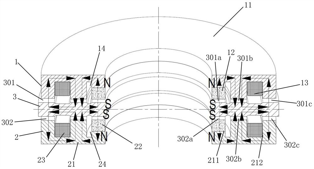
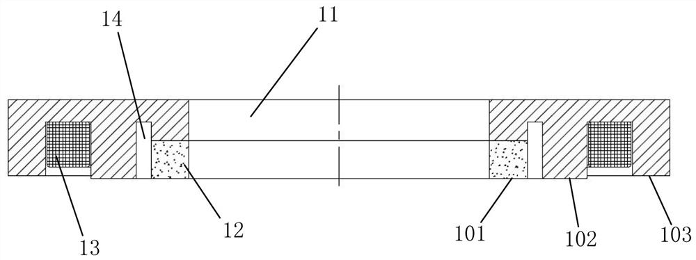
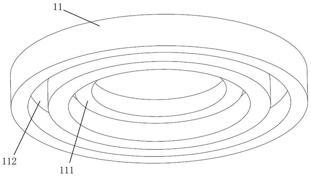
Permanent magnet biased axial magnetic bearing
A technology of axial magnetic bearing and permanent magnetic bias, which is applied in the field of magnetic suspension to achieve uniform air gap, reduce power consumption, improve dynamic response speed and control accuracy
- Summary
- Abstract
- Description
- Claims
- Application Information
AI Technical Summary
Problems solved by technology
Method used
Image

Examples
Embodiment Construction
[0023] In order to make the purpose, technical solutions and advantages of the embodiments of the present invention clearer, the technical solutions in the embodiments of the present invention will be clearly and completely described below in conjunction with the drawings in the embodiments of the present invention. Obviously, the described embodiments It is a part of embodiments of the present invention, but not all embodiments. Based on the embodiments of the present invention, all other embodiments obtained by persons of ordinary skill in the art without making creative efforts belong to the protection scope of the present invention. It should be noted that, in the case of no conflict, the embodiments in the present application and the features in the embodiments can be combined arbitrarily with each other.
[0024] The invention adopts the permanent magnet to provide the bias magnetic flux without the bias current, and reduces the power consumption of the magnetic bearing;...
PUM
 Abstract
Description
Claims
Application Information