Self-pressure sealing stop valve

A shut-off valve and self-pressure technology, which is used in lift valves, valve devices, engine components, etc., can solve the problems of gaps in the sealing joint surface, inability to seal the gaps, and poor self-sealing effect of the shut-off valve. The effect of leakage

Inactive Publication Date: 2020-11-13
NEWMAN (YANCHENG) VALVE MFG CO LTD
View PDF0 Cites 3 Cited by
  • Summary
  • Abstract
  • Description
  • Claims
  • Application Information

AI Technical Summary

Problems solved by technology

The existing stop valve is mainly composed of a valve body, a valve cover, a valve stem and a valve plate. A sealing gasket is provided between the valve plate and the valve body to seal the medium and prevent the medium from passing along the gap between the valve plate and the valve body. Leakage, but due to the high pressure of the flowing medium in the valve, and the pressure generally acts on the joint between the gasket and the valve plate, the gasket and the valve body (hereinafter collectively referred to as the sealing joint surface), so too much The high pressure of the flowing medium will form a separation effect on the sealing joint surface, so that the sealing joint surface tends to produce gaps, which will cause the flowing medium to easily penetrate outward through the sealing joint surface, thereby affecting the sealing performance
[0003] The self-sealing effect of the existing stop valve is poor, resulting in gaps easily occurring at the sealing joints, and the valve plate will be severely worn during frequent switch use, resulting in the inability to effectively seal the gaps, so that the internal liquid or Gas leakage endangers the health of users

Method used


Image

  • Self-pressure sealing stop valve
  • Self-pressure sealing stop valve
  • Self-pressure sealing stop valve

Examples


Embodiment Construction

[0028] The present invention will be described in further detail below in conjunction with the accompanying drawings and embodiments, so that those skilled in the art can implement it with reference to the description.

[0029] It should be understood that terms such as "having", "comprising" and "including" used herein do not exclude the presence or addition of one or more other elements or combinations thereof.

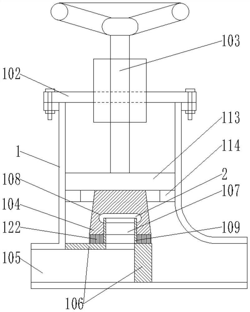
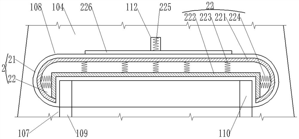
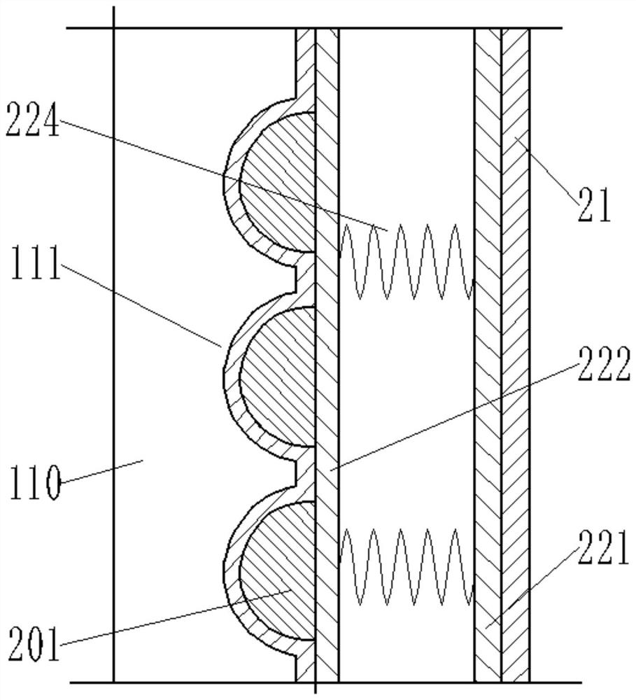
[0030] Such as Figure 1-Figure 8 As shown, the present invention provides a self-pressure sealing stop valve, comprising:

[0031] The stop valve body 1, the upper end of the stop valve body 1 is provided with a valve cover 102, and the valve cover 102 is provided with a valve stem 103, the lower end of the valve stem 103 passes through the valve cover 102 and extends to the In the shut-off valve body 1, the lower end of the valve stem 103 is connected with a valve plate 104, the left side of the shut-off valve body 1 is a water inlet chamber 105, the middle is a ...


PUM


Abstract

The invention discloses a self-pressure sealing stop valve. The self-pressure sealing stop valve comprises a stop valve body, a valve deck is arranged at the upper end of the stop valve body, a valverod is rotationally arranged on the valve deck, the lower end of the valve rod penetrates through the valve deck and extends into the stop valve body, the lower end of the valve rod is connected witha valve plate, a water inlet cavity is formed in the left side of the stop valve body, a valve seat and a water outlet cavity are formed in the right side, an inner screw hole is formed in the lower surface of the valve plate, a first inner groove is formed in the inner top face of the inner screw hole, the inner diameter of the first inner groove is larger than that of the inner screw hole, an air bag mechanism is arranged in the first inner groove, a valve seat barrel is arranged on the valve seat, and an outer thread corresponding to the inner screw hole is arranged on the outer surface ofthe valve seat barrel. The valve plate is selectively connected with the valve seat cylinder in a sealed mode. According to the self-pressure sealing stop valve, the valve plate enables the valve seatcylinder to be connected in a threaded mode, so that the valve seat cylinder is sealed by the air bag mechanism in the first inner groove, cutting off of media is achieved, gaps are not prone to being generated at the sealing joint, and leakage is avoided.

Description

technical field [0001] The invention relates to the technical field of shut-off valves, and more specifically, the invention relates to a self-pressure sealing shut-off valve. Background technique [0002] There are many types of valves on the pipeline, among which the stop valve is a commonly used valve, which is used to control the cutting of various fluid media such as air, water, steam or adjust the flow rate. The opening and closing parts of the stop valve are plug-shaped The sealing surface of the valve plate is flat or conical, and the valve plate moves linearly with the valve stem rising and falling. The existing stop valve is mainly composed of a valve body, a valve cover, a valve stem and a valve plate. A sealing gasket is provided between the valve plate and the valve body to seal the medium and prevent the medium from passing along the gap between the valve plate and the valve body. Leakage, but due to the high pressure of the flowing medium in the valve, and th...

Claims


Application Information

Patent Timeline
Patent Type & Authority Applications(China)
IPC IPC(8): F16K1/00F16K1/36F16K1/46F16K1/32B08B1/04
CPCB08B1/002B08B1/04F16K1/00F16K1/32F16K1/36F16K1/46
Inventor 孙晋朱金华高明汤雯娟
Owner NEWMAN (YANCHENG) VALVE MFG CO LTD
Why Eureka
Try Eureka