dehumidifier

A technology for dehumidifiers and bodies, applied in mechanical equipment, heating methods, lighting and heating equipment, etc., can solve the problems of low safety performance of dehumidifiers, achieve the effect of improving intelligent control and avoiding safety threats

Active Publication Date: 2021-07-23
GREE ELECTRIC APPLIANCES INC
View PDF6 Cites 0 Cited by
  • Summary
  • Abstract
  • Description
  • Claims
  • Application Information

AI Technical Summary

Problems solved by technology

[0004] The main purpose of the present invention is to provide a dehumidifier to solve the problem of low safety performance of the dehumidifier in the prior art

Method used


Image

  • dehumidifier
  • dehumidifier
  • dehumidifier

Examples


Embodiment Construction

[0026] It should be noted that, in the case of no conflict, the embodiments in the present application and the features in the embodiments can be combined with each other. The present invention will be described in detail below with reference to the accompanying drawings and examples.

[0027] It should be noted that the terminology used here is only for describing specific implementations, and is not intended to limit the exemplary implementations according to the present application. As used herein, unless the context clearly dictates otherwise, the singular is intended to include the plural, and it should also be understood that when the terms "comprising" and / or "comprising" are used in this specification, they mean There are features, steps, operations, means, components and / or combinations thereof.

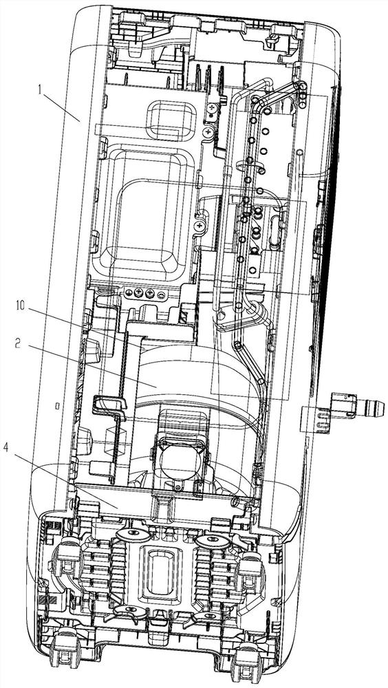
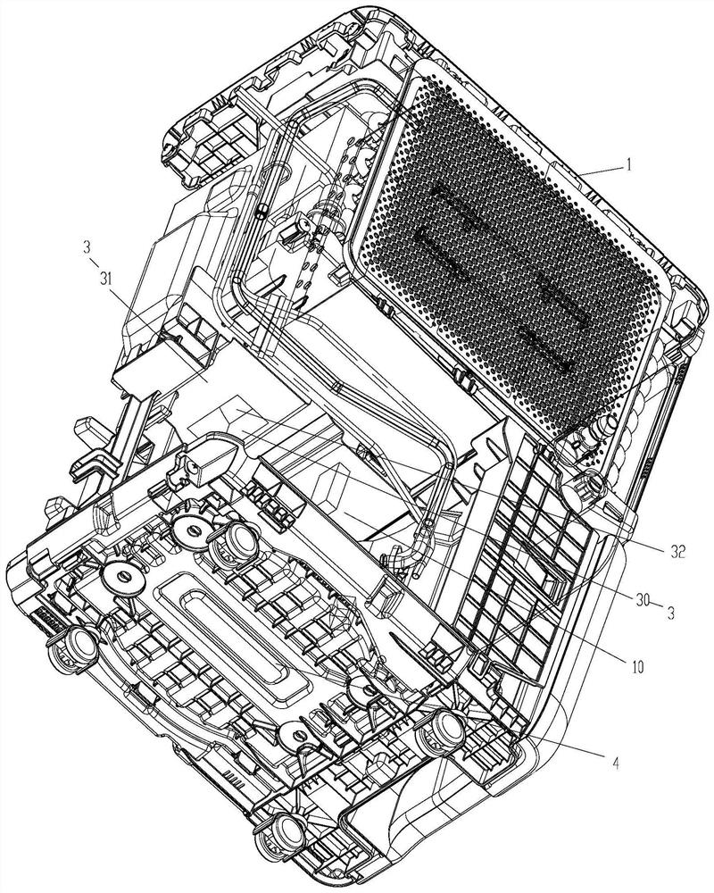
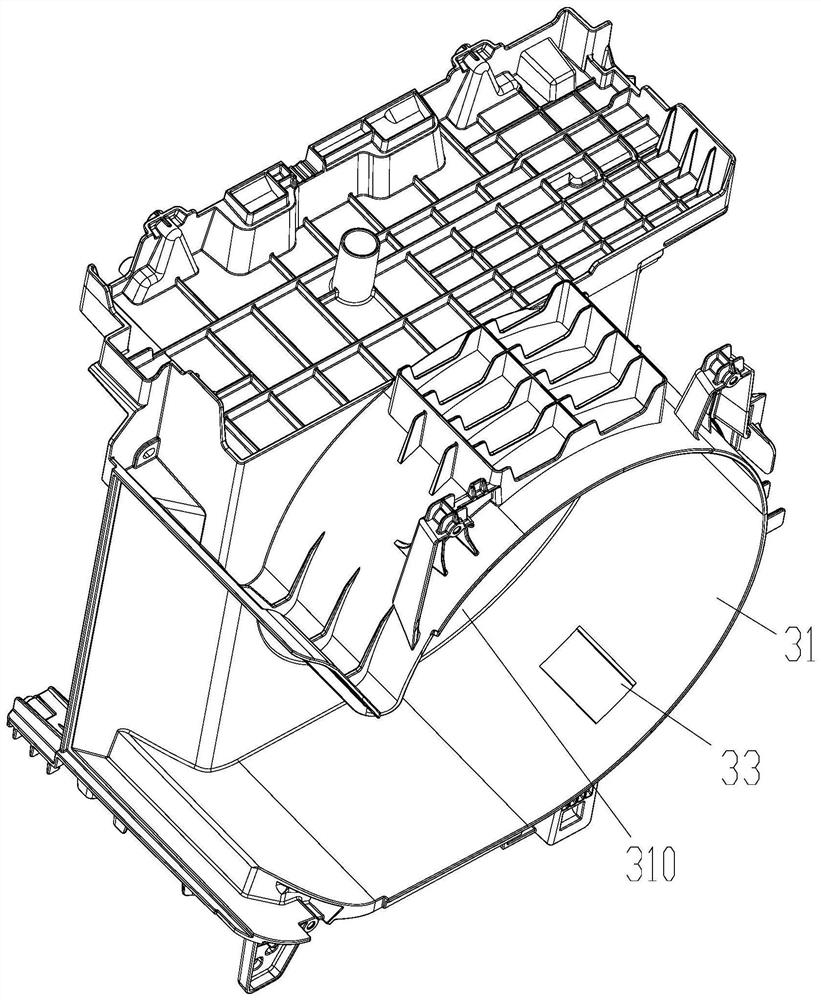
[0028] The present invention provides a dehumidifier, please refer to Figure 1 to Figure 5 , including: a body 1, an installation cavity 10 is arranged in the body 1; a c...


PUM


Abstract

The invention provides a dehumidifier, comprising: a body, an installation cavity is arranged in the body; a compressor is installed in the installation cavity; an exhaust assembly, the exhaust assembly has an exhaust channel, and the exhaust channel communicates with the installation cavity to The airflow in the installation cavity is discharged through the exhaust channel; the concentration detection module, at least part of the concentration detection module is installed in the installation cavity, and is used to detect the concentration of the refrigerant in the installation cavity, so as to control the exhaust air according to the concentration of the refrigerant in the installation cavity The channel is opened or closed. To solve the problem of low safety performance of the dehumidifier in the prior art.

Description

technical field [0001] The invention relates to the field of dehumidifiers, in particular to a dehumidifier. Background technique [0002] At present, the pressure of environmental protection is becoming more and more severe, and all walks of life have put the concept of environmental protection on the agenda; taking dehumidifiers as an example, the widely used environmentally friendly refrigerants are mainly R290 and R32. [0003] However, the compressor and the electrical box in the dehumidifier are in a relatively closed space, and there is a certain probability that electric sparks will be generated when the compressor is turned on and off. If the dehumidifier leaks and accumulates in the compressor In the confined space near the machine system, the concentration reaches the lower limit of deflagration, and in case of poor contact of the terminals of the press or the action of the control components in the electrical box, an electric spark of the ignition source is gener...

Claims


Application Information

Patent Timeline
Patent Type & Authority Patents(China)
IPC IPC(8): F24F3/14F24F11/36F24F13/00
CPCF24F3/14F24F13/00F24F11/36
Inventor 李岗梁绍康李和坤王朋政李书东
Owner GREE ELECTRIC APPLIANCES INC
Why Eureka
Try Eureka