
Heat exchanger and temperature control circuit system

A heat exchanger and loop system technology, applied in heat exchange equipment, water heaters, indirect heat exchangers, etc., can solve the problems of space consumption, material and weight, high cost, etc., and achieve the effect of saving space

Inactive Publication Date: 2020-11-13
KONVEKTA
View PDF13 Cites 0 Cited by
  • Summary
  • Abstract
  • Description
  • Claims
  • Application Information

AI Technical Summary

Problems solved by technology

Thus, although it is possible, for example, to preheat the second fluid and thus the traction battery before a cold start, such an electrically operable heating device, which is additionally integrated in the fluid circuit carrying the second fluid, consumes an unnecessarily large amount of space, material and weight, resulting in correspondingly high costs

Method used


Image

  • Heat exchanger and temperature control circuit system
  • Heat exchanger and temperature control circuit system
  • Heat exchanger and temperature control circuit system

Examples


Embodiment Construction

[0034] All figures are to be understood schematically. In order to improve the clarity of the view, illustrations that are correct in scale have been omitted.

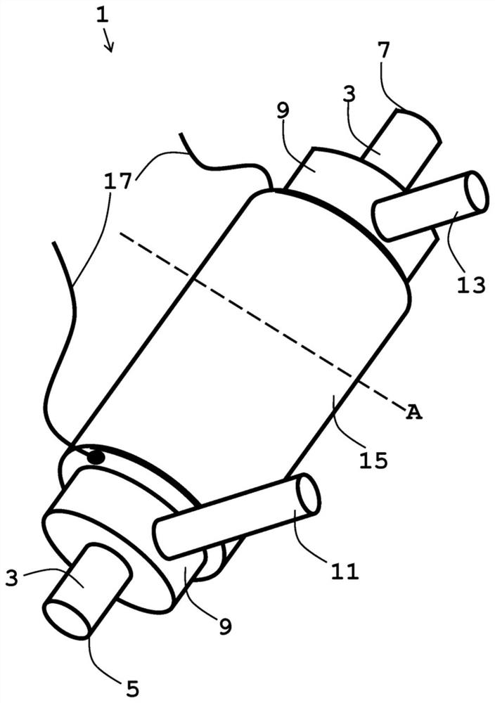
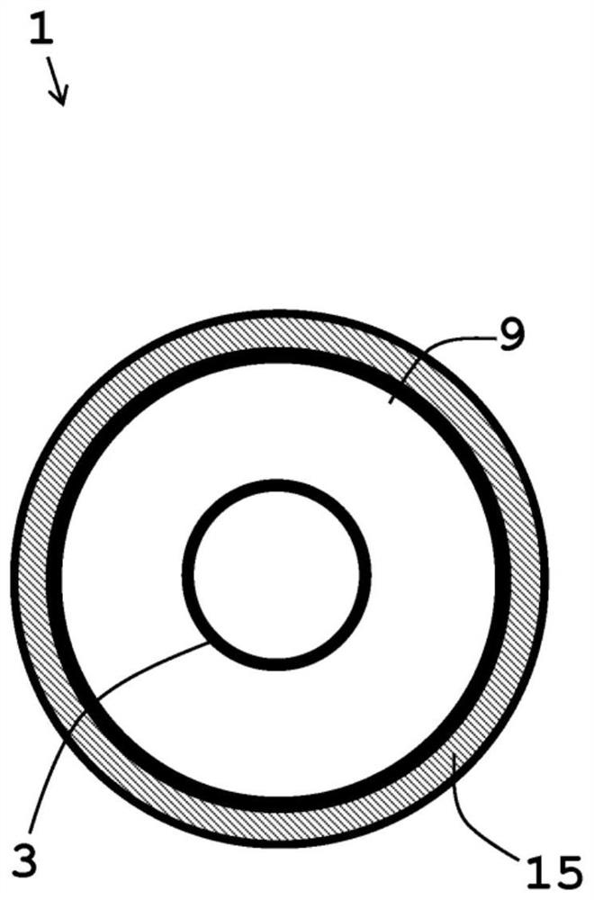
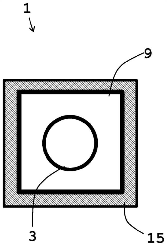
[0035] exist Figure 1a An exemplary embodiment of a heat exchanger 1 is shown in FIG. 1 , which is designed as a fluid-fluid heat exchanger. The line 3 for the first fluid runs in its interior in the direction of the longitudinal axis. The line 3 can be integrated into a fluid circuit by means of its front connection end 5 and its rear connection end 7 . The line 3 is formed as a refrigerant line. The line is suitable for allowing a refrigerant such as R-134a, R-1234yf or R-744 to flow through the line. The line is tubular in shape with a circular cross section. Its tube walls are made of steel or other commonly used materials suitable for this purpose. The line 3 runs coaxially with the line 9 for the second fluid in this line 9 . The line 9 likewise has a tubular shape with a circular cross section, wherein t...


PUM


Abstract

The invention relates to a heat exchanger (1). The heat exchanger has at least one pipeline (3) for a first fluid, which can be integrated into a fluid loop, and at least one pipeline (9) for a secondfluid, which can be integrated into a further fluid loop and used for heat exchange connection for the heat exchange of the first fluid with the second fluid. The heat exchanger (1) comprises at least one electrically operable heating element (15) which is arranged in a thermally conductive connection to at least one of the at least one pipeline (9) for the second fluid. The invention also relates to a circuit system and to a vehicle having such a circuit system.

Description

technical field [0001] The invention relates to a heat exchanger with at least one line for a first fluid which can be integrated into a fluid circuit and for which a heat exchange device for the heat exchange of the first fluid with a second fluid is provided. In the exchange connection, at least one line for the second fluid can be integrated into another fluid circuit. Such heat exchangers, also known as fluid-fluid heat exchangers, are used in particular in air-conditioning installations for vehicles which have a circuit system with a refrigerant circuit and a cooling circuit for the fluid in both circuits heat exchange between them. Furthermore, the invention relates to a loop system and a vehicle having said loop system. The circuit system comprises: a first fluid circuit having at least one compressor, a condenser / gas cooler and an expansion mechanism for a first fluid circulated therein as a refrigerant; and a second fluid circuit, the second cooling circuit has at ...

Claims


Application Information

Patent Timeline
IPC IPC(8): F28D7/10F28F7/00B60H1/00
CPCF28D7/10F28F7/00B60H1/00342F28D7/103F28D7/106F28D2021/008F28D2021/0068H01M10/625H01M10/663F25B5/00F25B9/008F25B25/005F25B49/02F25B2600/2519Y02E60/10F24H1/009F24H1/102F24H1/121F24H1/142F24H2250/02H05B2203/021B60H1/00278B60H1/00321B60H1/2215B60H1/2221B60H1/3227H05B3/42
Inventor 迈克尔·索纳卡尔布亚历山大·克尼里姆
Owner KONVEKTA
Learn More