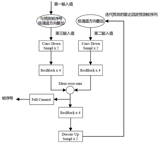
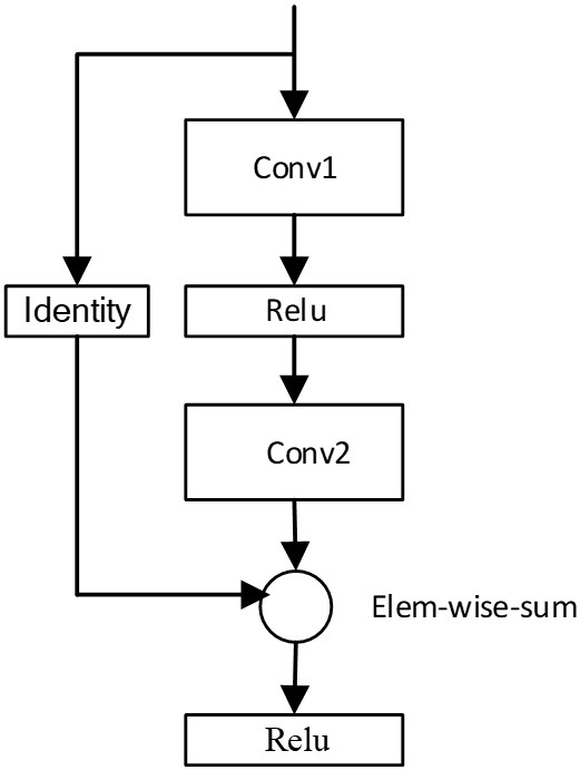
Method and equipment for determining sequence of radar echo prediction frames
A technology of radar echo and frame prediction, which is applied in radio wave measurement system, radio wave reflection/re-radiation, measurement device and other directions, can solve the problem of low accuracy of radar echo and achieve good practical effect.
- Summary
- Abstract
- Description
- Claims
- Application Information
AI Technical Summary
Problems solved by technology
Method used
Image


Examples
Embodiment Construction
[0051] The present invention will be described in further detail below in conjunction with the accompanying drawings.
[0052] In a typical configuration of the present application, each module and trusted party of the system includes one or more processors (CPU), input / output interface, network interface and memory.
[0053] Memory may include non-permanent storage in computer-readable media, in the form of random access memory (RAM) and / or nonvolatile memory, such as read-only memory (ROM) or flash RAM. Memory is an example of computer readable media.
[0054] Computer-readable media, including both permanent and non-permanent, removable and non-removable media, can be implemented by any method or technology for storage of information. Information may be computer readable instructions, data structures, modules of a program, or other data. Examples of computer storage media include, but are not limited to, phase change memory (PRAM), static random access memory (SRAM), dynami...
PUM
 Abstract
Description
Claims
Application Information
 - R&D
- Intellectual Property
- Life Sciences
- Materials
- Tech Scout
- Unparalleled Data Quality
- Higher Quality Content
- 60% Fewer Hallucinations
Browse by: Latest US Patents, China's latest patents, Technical Efficacy Thesaurus, Application Domain, Technology Topic, Popular Technical Reports.
© 2025 PatSnap. All rights reserved.Legal|Privacy policy|Modern Slavery Act Transparency Statement|Sitemap|About US| Contact US: help@patsnap.com