
Camera blocking area detection method and device, equipment and storage medium

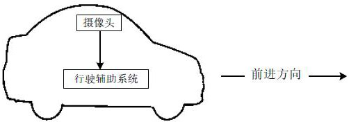
An occlusion detection and camera technology, applied in the field of computer vision, can solve problems such as difficult to apply camera occlusion detection analysis, unsuitable vehicles/robots, difficult vehicle/robot camera occlusion detection, etc.

Active Publication Date: 2020-11-13
SHENZHEN MINIEYE INNOVATION TECH CO LTD
View PDF7 Cites 5 Cited by
  • Summary
  • Abstract
  • Description
  • Claims
  • Application Information

AI Technical Summary

Problems solved by technology

[0004] However, the traditional camera occlusion detection algorithm is generally designed for cameras in static scenes such as indoors or cars, and can only analyze the camera occlusion when the vehicle / robot is stationary, which is greatly affected by factors such as noise and illumination changes. The stickiness is not high, and it is difficult to detect the occlusion of the camera during the driving process of the vehicle / robot; although the corner optical flow algorithm can detect the occlusion of the camera during driving, the corner optical flow algorithm is mainly based on the angle of the multi-frame image. Point optical flow information is used for occlusion detection, which is not suitable for camera occlusion analysis of vehicles / robots in a stationary state
[0005] It can be seen that since the driving scene includes the dynamic process during driving and the static process when stationary, the above-mentioned camera occlusion detection algorithms are difficult to apply to the camera occlusion detection analysis of the driving scene.

Method used


Image

  • Camera blocking area detection method and device, equipment and storage medium
  • Camera blocking area detection method and device, equipment and storage medium
  • Camera blocking area detection method and device, equipment and storage medium

Examples


Embodiment Construction

[0042] In order to make the purpose, technical solution and advantages of the present application clearer, the present application will be further described in detail below in conjunction with the accompanying drawings and embodiments. It should be understood that the specific embodiments described here are only used to explain the present application, and are not intended to limit the present application.

[0043] Reference in this application to an "embodiment" means that a particular feature, structure, or characteristic described in connection with the embodiment can be included in at least one embodiment of the present application. The occurrences of this phrase in various places in the specification are not necessarily all referring to the same embodiment, nor are separate or alternative embodiments mutually exclusive of other embodiments. It is understood explicitly and implicitly by those skilled in the art that the embodiments described in this application can be comb...


PUM


Abstract

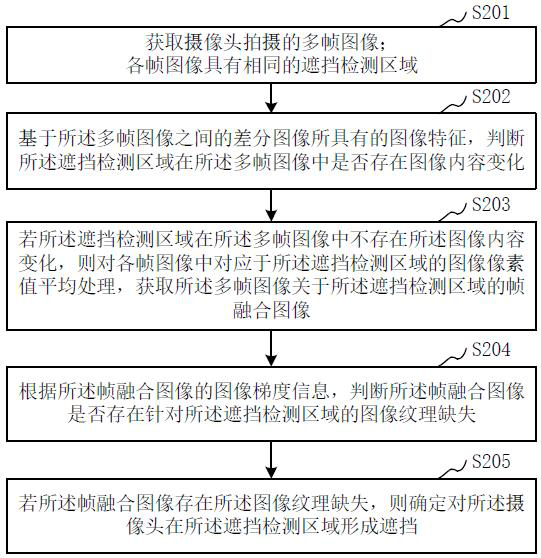
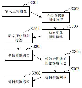
The invention provides a camera blocking area detection method and device, equipment and a storage medium. The method comprises the steps of acquiring multiple frames of images shot by a camera, wherein each frame of image has the same blocking detection area; based on the image features of the differential images among the multiple frames of images, judging whether the image content of the blocking detection area changes in the multiple frames of images or not; if the image content of the blocking detection area does not change in the multiple frames of images, averaging the image pixel values corresponding to the blocking detection area in each frame of image, and obtaining a frame fusion image of the multiple frames of images about the blocking detection area; according to the image gradient information of the frame fusion image, judging whether the frame fusion image has image texture missing for the blocking detection area or not; and if the frame fusion image has image texture missing, determining that the camera forms blocking in the blocking detection area, thereby realizing real-time analysis of camera blocking detection, and being suitable for camera blocking detection ina driving scene.

Description

technical field [0001] The present application relates to the technical field of computer vision, and in particular to a method, device, computer equipment and storage medium for detecting an area blocked by a camera. Background technique [0002] Based on the image acquisition function of the camera, most driving assistance systems will use the camera as one of the visual sensors to achieve driving assistance, such as the advanced driving assistance system (Advanced Driving Assistant System, ADAS system) of the vehicle and the driving assistance system of the robot; among them , the camera's ability to capture images normally plays an important role in ensuring the normal operation of the driving assistance system. [0003] During long-term use, the camera is likely to be unable to collect clear road scene images due to dust, oil stains, or hardware failures, and there are certain information blind spots in the collected images; Images with information blind spots collecte...

Claims


Application Information

Patent Timeline
IPC IPC(8): G06T7/44G06T7/254
CPCG06T2207/10016G06T2207/20224G06T2207/30252G06T7/254G06T7/44
Inventor 程飞洋郑伟杨广刘国清
Owner SHENZHEN MINIEYE INNOVATION TECH CO LTD
Learn More