
Camera module and mobile terminal

A camera module and lens assembly technology, applied in the field of camera modules and mobile terminals, can solve the problems of dust-catching glue and stray light, and achieve the effect of flexible application, simple operation and solving the problem of glue

Pending Publication Date: 2020-11-13
KUNSHAN Q TECH CO LTD
View PDF0 Cites 0 Cited by
  • Summary
  • Abstract
  • Description
  • Claims
  • Application Information

AI Technical Summary

Problems solved by technology

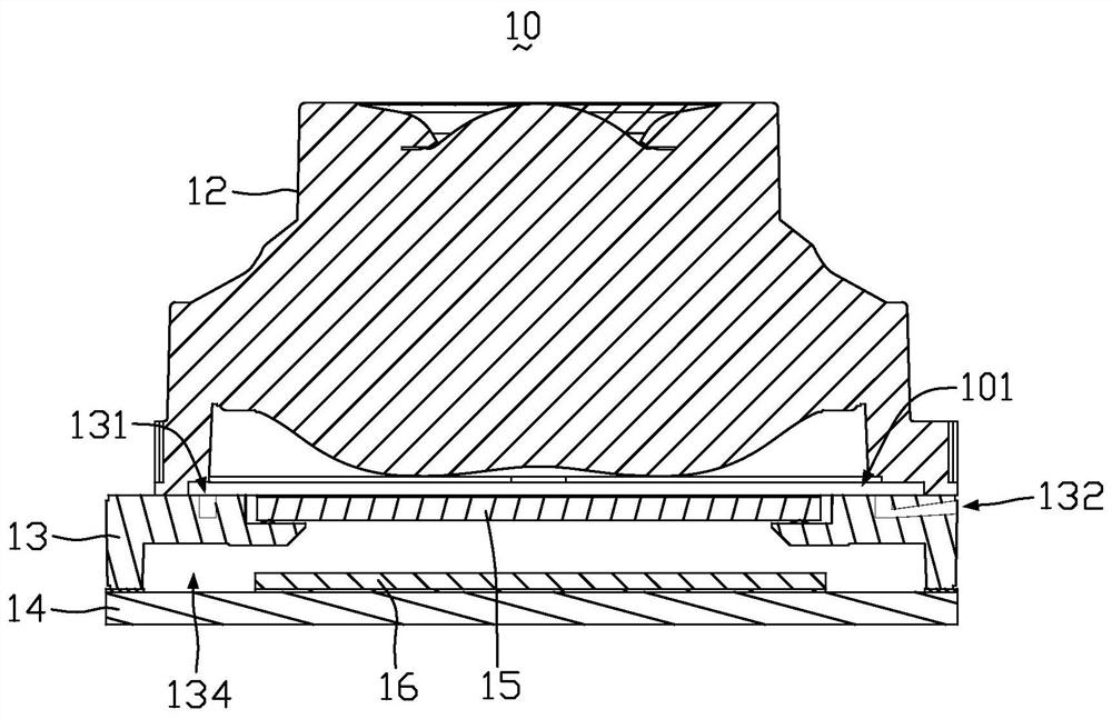
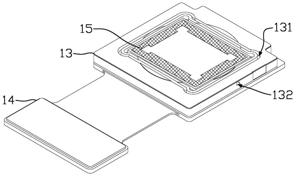
[0006] In view of this, the present invention provides a camera module and a mobile terminal, which can solve the problem of stray light caused by the reflection of the dust-catching glue. If it is necessary to reapply the dust-catching glue, it is not necessary to disassemble the lens assembly from the supporting base , or disassemble the voice coil motor assembly from the support base, the method is simple, and the dust glue can be used at any time or not, and the use is flexible

Method used


Image

  • Camera module and mobile terminal
  • Camera module and mobile terminal
  • Camera module and mobile terminal

Examples


no. 2 example

[0038] Figure 9 It is an exploded view of the camera module according to the second embodiment of the present invention. Such as Figure 9 As shown, the structure of the camera module 10 of this embodiment is substantially the same as that of the camera module 10 of the first embodiment, except that the lens assembly 12 of this embodiment includes a voice coil motor assembly 122 .

[0039] Figure 10 It is a partial cross-sectional structural schematic diagram of the camera module according to the second embodiment of the present invention. Such as Figure 9 and Figure 10 As shown, specifically, the lens assembly 12 includes a lens 121 and a voice coil motor assembly 122, the lens 121 is assembled into the voice coil motor assembly 122, the voice coil motor assembly 122 drives the lens 121 to move, and the voice coil motor assembly 122 is arranged on the supporting base 13 , the supporting base 13 is disposed on the circuit substrate 14 , and the photosensitive chip 16 ...


PUM


Abstract

The invention relates to a camera module which comprises a supporting base and an optical filter, the optical filter is arranged on the supporting base, a groove and a glue inlet channel are formed inthe supporting base, the glue inlet channel comprises a glue inlet and a glue outlet, the glue outlet is communicated with the groove, the glue inlet is formed in the peripheral surface of the supporting base, and the groove is located around the optical filter. The camera module can solve the problem of stray light caused by light reflection of the dust catching glue, and if the dust catching glue needs to be supplemented, the lens assembly does not need to be disassembled from the supporting base or the voice coil motor assembly does not need to be disassembled from the supporting base, themethod is simple, the dust catching glue can be sprayed or not sprayed at any time, and the camera module is flexible to use; the dust capturing glue is located around the optical filter and is not under the lens, when the lens descends, the dust capturing glue does not make contact with glue, and the gluing problem is solved. The invention also relates to a mobile terminal.

Description

technical field [0001] The invention relates to the technical field of imaging equipment, in particular to a camera module and a mobile terminal with the camera module. Background technique [0002] Existing camera modules are generally composed of photosensitive chips, lenses, filters, motors, motor bases, and flat substrates. The electrical signal generated by the photosensitive chip is output through the connection point between the bottom of the chip and the plane substrate. The lens is set in the motor, the filter is bonded to the motor base, and the motor base is bonded to the plane substrate. The lens and the motor form a The components are glued on top of the motor base. After assembling the motor base and the filter components of the existing camera module, it is necessary to draw dust-catching glue on the filter to remove dirt. The position of the dust-catching glue is on the surface of the filter. On the black silk screen, cover the lens and motor components aft...

Claims


Application Information

Patent Timeline
Patent Type & Authority Applications(China)
IPC IPC(8): H04N5/225
CPCH04N23/52H04N23/57H04N23/55H04N23/54
Inventor 许杨柳颜欢欢邓爱国
Owner KUNSHAN Q TECH CO LTD
Learn More