Eureka AIR delivers breakthrough ideas for toughest innovation challenges, trusted by R&D personnel around the world.

Tibia outer side locking plate finish machining positioning and drilling device

A technology for drilling devices and locking plates, applied in positioning devices, boring/drilling, metal processing equipment, etc., can solve the problem of adjusting the distance between the second clamping plate and the first clamping plate, inconvenient disassembly, Inability to dissipate heat and other problems, to achieve the effects of quick replacement, improved versatility, and extended service life

Pending Publication Date: 2020-11-17
上海翰利医疗科技有限公司
View PDF0 Cites 3 Cited by
  • Summary
  • Abstract
  • Description
  • Claims
  • Application Information

AI Technical Summary

Problems solved by technology

[0003] However, there are still some disadvantages in the existing tibial lateral locking plate finishing and positioning drilling device. When drilling the locking plate, the distance between the second clamping plate and the first clamping plate cannot be adjusted according to the size of the locking plate. The problem of adjusting; in addition, when the reversing motor is working, it will generate a certain amount of heat, and there is a problem that it cannot dissipate heat. In addition, when the drill bit is used for a long time, the surface of the drill bit will be worn to varying degrees, which is inconvenient Disassembly problem, for which we propose a positioning drilling device for finishing the lateral tibial locking plate

Method used


Image

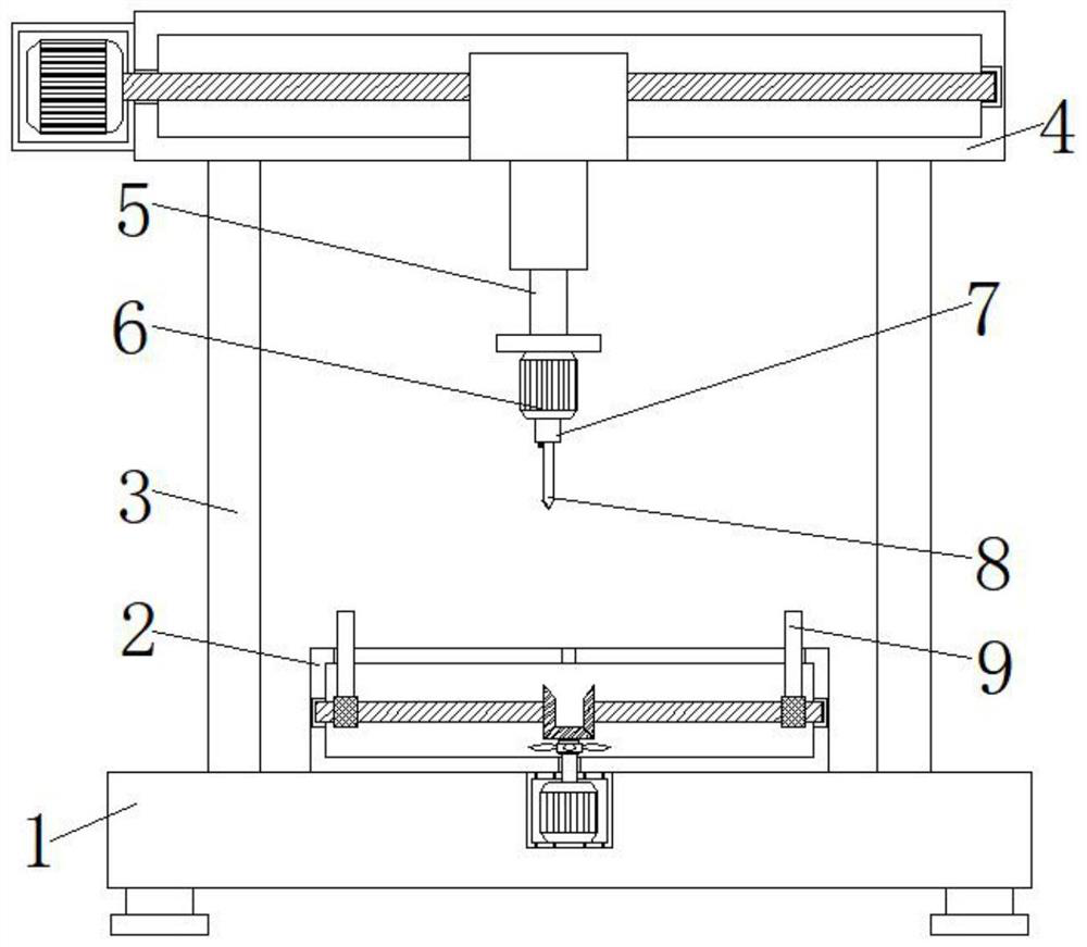
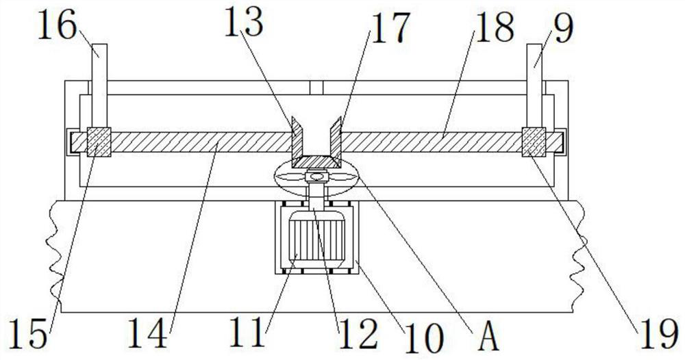
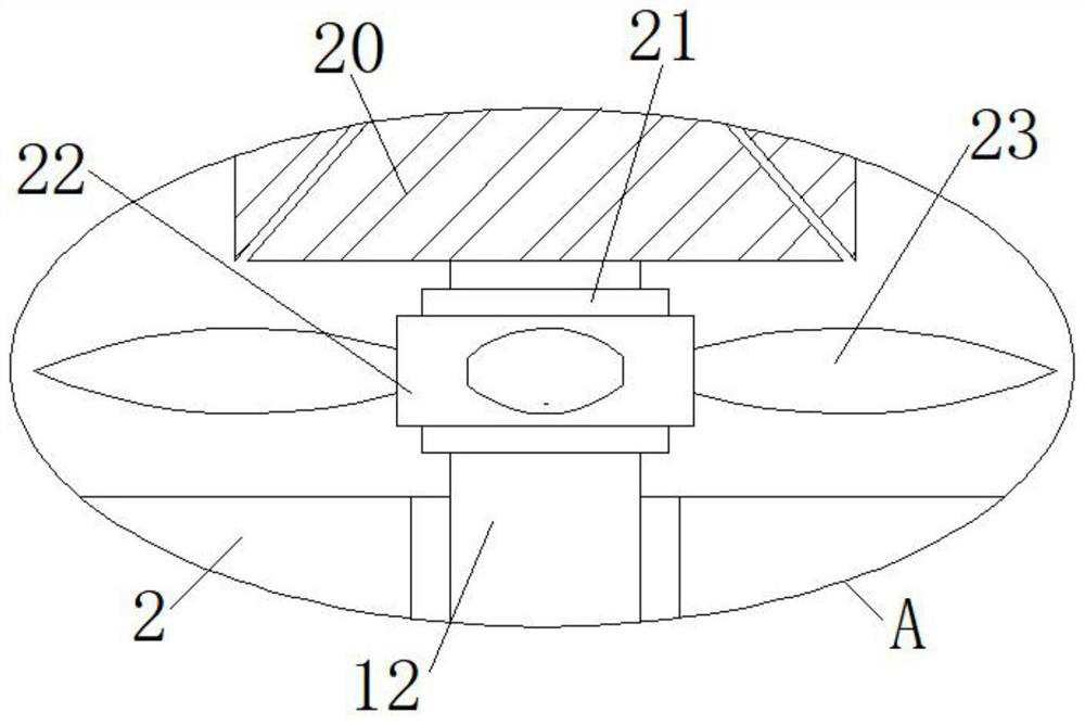
  • Tibia outer side locking plate finish machining positioning and drilling device
  • Tibia outer side locking plate finish machining positioning and drilling device
  • Tibia outer side locking plate finish machining positioning and drilling device

Examples


Embodiment Construction

[0024] In order to make the technical means, creative features, goals and effects achieved by the present invention easy to understand, the present invention will be further elaborated below in conjunction with specific embodiments, but the following embodiments are only preferred embodiments of the present invention, not all. Based on the examples in the implementation manners, other examples obtained by those skilled in the art without making creative efforts all belong to the protection scope of the present invention. The experimental methods in the following examples, unless otherwise specified, are conventional methods, and the materials, reagents, etc. used in the following examples, unless otherwise specified, can be obtained from commercial sources.

[0025] Example:

[0026] Such as Figure 1-Figure 3 As shown, a tibial lateral locking plate finishing positioning drilling device, including a base 1, the top surface of the base 1 is fixed with a workbench 2, the cavit...


PUM


Abstract

The invention discloses a tibia outer side locking plate finish machining positioning and drilling device. The device comprises a base, a workbench is fixed to the surface of the top end of the base,a mounting frame is fixed to a cavity of the base, a forward and reverse rotation motor is fixed to the inner side of the mounting frame, and an output shaft of the forward and reverse rotation motoris rotationally connected with a rotating shaft. The rotating shaft rotationally penetrates through the outer wall of the bottom end of the workbench, the rotating shaft extends to a cavity of the workbench, a third bevel gear is fixed to the tail end of the rotating shaft, and the two sides of the third bevel gear are in engaged connection with a first bevel gear and a second bevel gear correspondingly. Through the arrangement of the forward and reverse rotation motor, the distance between clamping mechanisms can be conveniently and rapidly adjusted, and the positioning effect of the clampingmechanisms on a locking steel plate is guaranteed; through the arrangement of fan blades, wind power generated when the fan blades rotate can cool the forward and reverse rotation motor in a workingstate; and through the arrangement of the fan blades, a drill bit can be conveniently and rapidly replaced, and the drilling effect of the drill bit on the locking steel plate is guaranteed.

Description

technical field [0001] The invention relates to the technical field of positioning drilling devices, in particular to a positioning drilling device for finishing the lateral tibial locking plate. Background technique [0002] Locking plate, is a fracture fixation device with locking threaded holes. The locking plate makes the combination of bone and plate stronger, making the amputated limb more stable after reduction. The positioning drilling device is needed in the processing and production of the locked steel plate; the positioning drilling device refers to the general name of the equipment used to process holes on solid materials. Common drilling devices include electric drills, drilling machines, etc. With further development, the efficiency of the drilling device has also been greatly improved. [0003] However, there are still some disadvantages in the existing tibial lateral locking plate finishing and positioning drilling device. When drilling the locking plate, t...

Claims


Application Information

Patent Timeline
Patent Type & Authority Applications(China)
IPC IPC(8): B23B41/00B23Q3/06B23Q11/12B23Q11/00
CPCB23B41/00B23Q3/06B23Q11/0032B23Q11/12
Inventor 张欣
Owner 上海翰利医疗科技有限公司
Why Eureka
Eureka Blog
Learn More