High-strength sheet metal machining working platform

A working platform and high-strength technology, applied in the field of sheet metal processing, can solve the problems of low cutting efficiency, potential safety hazards, poor adaptability, etc., and achieve the effects of stable cutting, improved efficiency, and improved friction

Inactive Publication Date: 2020-11-17
朱安学
View PDF9 Cites 6 Cited by
  • Summary
  • Abstract
  • Description
  • Claims
  • Application Information

AI Technical Summary

Problems solved by technology

[0003] We cannot do without sheet metal parts everywhere in our life. Cutting platforms are often used in the process of sheet metal parts processing. When conventional cutting platforms are used for high-strength cutting, manual unloading is required, which leads to low cutting efficiency. Simultaneous cutting The splashing material generated during work may cause injury to people, posing a safety hazard, and the cutting angle of the conventional cutting platform is relatively fixed, resulting in poor adaptability. Therefore, a sheet metal cutting with strong adaptability and high-intensity work is required. platform

Method used


Image

  • High-strength sheet metal machining working platform
  • High-strength sheet metal machining working platform
  • High-strength sheet metal machining working platform

Examples


Embodiment 1

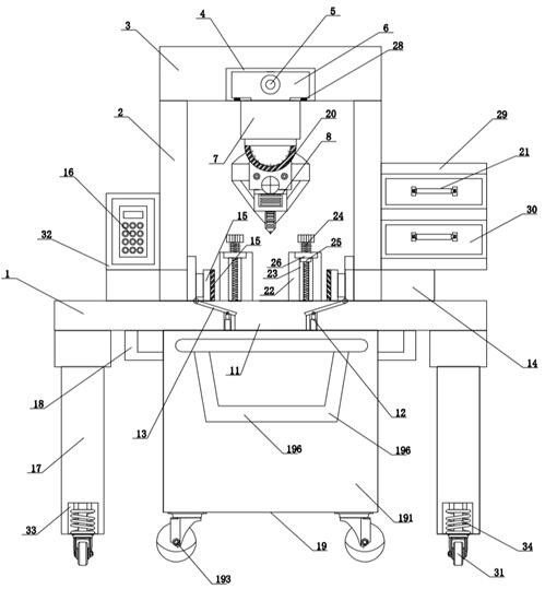
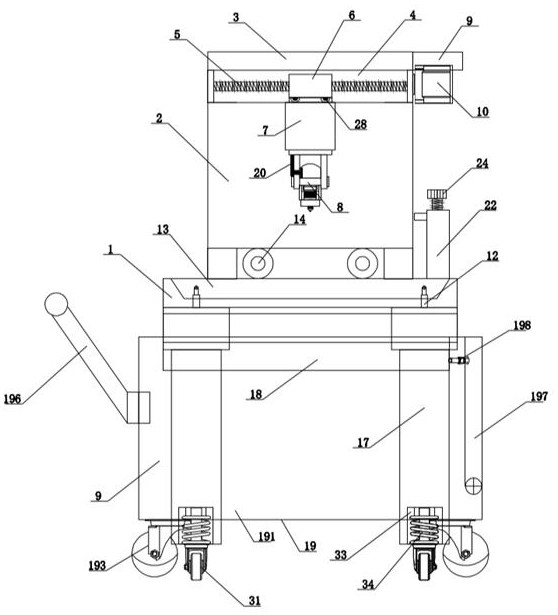
[0040] see figure 1 , a high-strength sheet metal processing work platform, including a base 1, a pair of mounting plates 2 are fixedly connected in the middle of the top of the base 1, a top plate 3 is fixedly connected to the top of the mounting plate 2, and the middle of the bottom of the top plate 3 is set There is a chute 4, a screw 5 is installed in the chute 4 through a ball bearing, the surface of the screw 5 is threaded with a slider 6, and the slider 6 is slidably connected in the chute 4, the slider 6 The bottom is fixedly connected with a telescopic cylinder 7, the bottom of the telescopic cylinder 7 is fixedly connected with a cutting mechanism 8, the back of the top plate 3 is fixedly connected with a fixed plate 9, the bottom of the fixed plate 9 is fixedly connected with a motor 10, and the output end of the motor 10 It is fixedly connected with the screw rod 5, and a cutting groove 11 is provided in the middle of the base 1, and a first electric push rod 12 is...


PUM


Abstract

The invention discloses a high-strength sheet metal machining working platform, and belongs to the field of sheet metal machining. The high-strength sheet metal machining working platform comprises abase, a pair of mounting plates are fixedly connected to the middle of the top of the base, a top plate is fixedly connected to the tops of the mounting plates, a sliding groove is formed in the middle of the bottom of the top plate, and a screw rod is mounted in the sliding groove through a ball bearing; the surface of the screw rod is in threaded connection with a sliding block, the sliding block is slidably connected into the sliding groove, the bottom of the sliding block is fixedly connected with a telescopic air cylinder, the bottom of the telescopic air cylinder is fixedly connected with a cutting mechanism, the back face of the top plate is fixedly connected with a fixing plate, the bottom of the fixing plate is fixedly connected with a motor, the output end of the motor is fixedlyconnected with the screw rod, and a cutting groove is formed in the middle of the base. According to the high-strength sheet metal machining working platform, angle adjustment can be carried out according to needs, meanwhile, cutting, discharging and conveying are convenient, the high-strength sheet metal machining working platform can adapt to high-strength cutting work, cutting is stable and accurate, functionality is high, and the high-strength sheet metal machining working platform is worthy of wide application and popularization.

Description

technical field [0001] The invention relates to the technical field of sheet metal processing, and more specifically relates to a high-strength sheet metal processing working platform. Background technique [0002] Sheet metal, a processing technology, sheet metal has not yet had a relatively complete definition. According to a definition in a foreign professional journal, it can be defined as: sheet metal is a comprehensive cold processing process for metal sheets, including shearing, punching / cutting / compositing, folding, riveting, splicing, forming, etc., its significant The feature is that the thickness of the same part is consistent. The products processed by the sheet metal industry are called sheet metal parts. The sheet metal parts referred to by different industries are generally different. The sheet metal parts that are mostly used for assembly are products processed by sheet metal technology. [0003] We cannot do without sheet metal parts everywhere in our life....

Claims


Application Information

Patent Timeline
Patent Type & Authority Applications(China)
IPC IPC(8): B23K26/38B23K26/70B23K37/04B23K26/08F16F15/067
CPCB23K26/38B23K26/702B23K37/0435B23K26/0869F16F15/067
Inventor 不公告发明人
Owner 朱安学
Why Eureka
Try Eureka