Supercharge Your Innovation With Domain-Expert AI Agents!

Novel multifunctional two-way chamfering machine and using method thereof

A multi-functional, chamfering machine technology, applied in the field of mechanical processing, can solve the problems of low processing efficiency, impact on processing accuracy, and impact on the health of equipment operators, and achieve the effects of improving work efficiency, improving product accuracy, and preventing hazards.

Pending Publication Date: 2020-11-17
天津市诚捷丰智能装备制造有限公司
View PDF0 Cites 9 Cited by
  • Summary
  • Abstract
  • Description
  • Claims
  • Application Information

AI Technical Summary

Problems solved by technology

[0002] In the mechanical processing industry, many parts need to be chamfered in order to reduce wear and prolong their service life after processing and forming, but the precision of the chamfer will affect the accuracy of the parts in the setting, so it is necessary to improve the precision of the chamfering machine At present, when the existing chamfering machine is processing square parts, the equipment operator needs to rotate the workpiece multiple times. Every time the operator rotates, it will affect the machining accuracy, and most of the chamfering machines can only be unilateral. Edge chamfering, low processing efficiency, cannot fully meet the needs of modern industrial production, equipment will generate a lot of dust during processing, if not treated, it will affect the health of equipment operators

Method used


Image

  • Novel multifunctional two-way chamfering machine and using method thereof
  • Novel multifunctional two-way chamfering machine and using method thereof
  • Novel multifunctional two-way chamfering machine and using method thereof

Examples


Embodiment 1

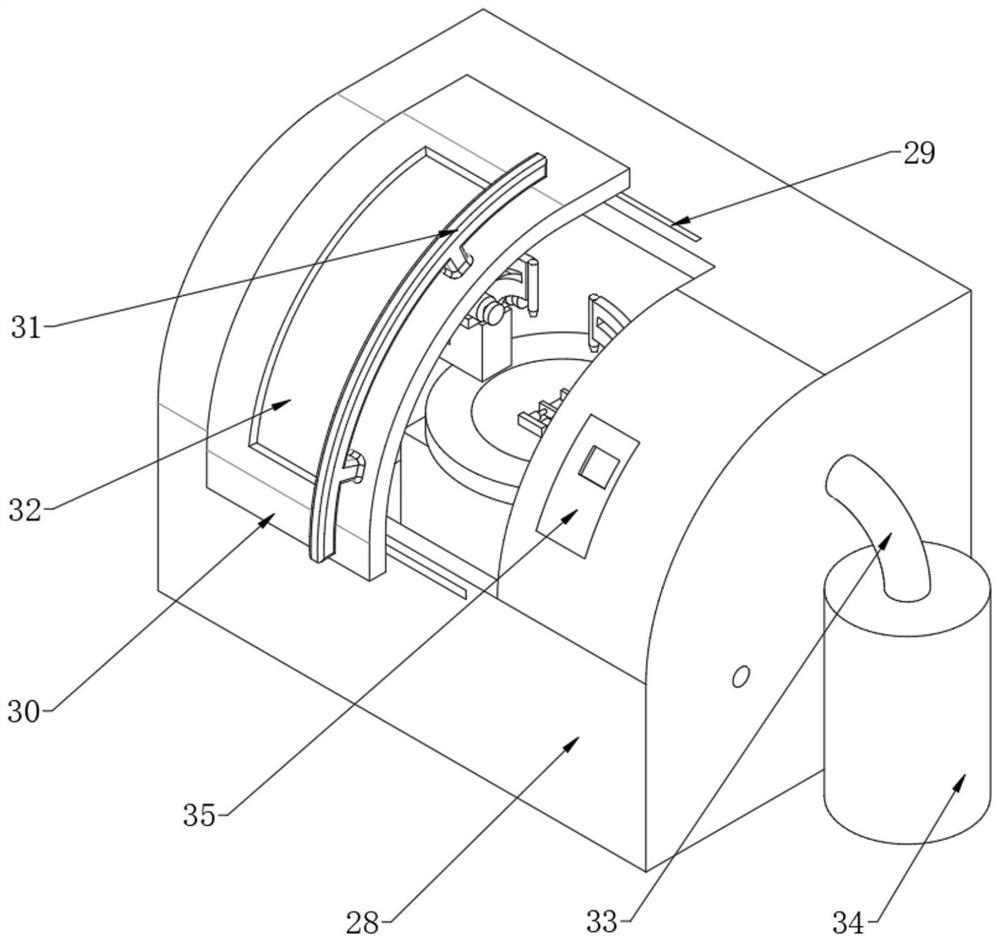
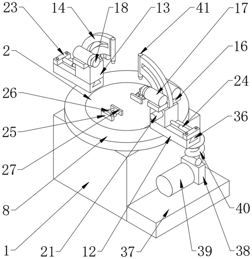
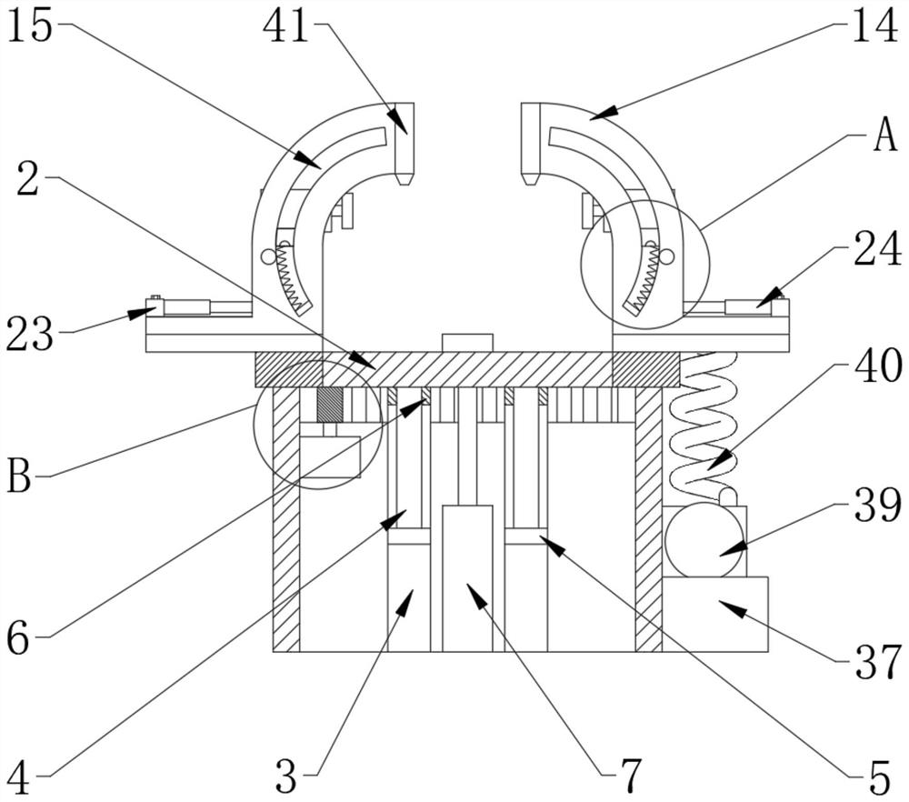
[0031] Such as Figure 1-5 As shown, a new multifunctional two-way chamfering machine and its use method include a base 1 and an operating table 2. The base 1 is a hollow cuboid structure inside the base 1. A hydraulic cylinder 7 is vertically fixed at the center of the inner bottom of the base 1. The hydraulic cylinder 7 The top output end is fixedly connected to the console 2, the inner bottom of the base 1 surrounds the hydraulic cylinder 7 and vertically fixes the support tube 3, the top of the support tube 3 fits closely with the console 2, and the top of the console 2 is symmetrically arranged with a second installation block 25 along the center , two second installation blocks 25 are fixedly installed on the opposite surface of the cylinder 26, the output end of the cylinder 26 is connected to the clamping block 27 by rotation, the bottom of the console 2 is located in the support tube 3 and the vertically fixed slide bar 4 is fixed, and the top of the base 1 is located ...


PUM


Abstract

The invention discloses a novel multifunctional two-way chamfering machine and a using method thereof. The novel multifunctional two-way chamfering machine comprises a base and an operation table; thebase is of a cuboid structure with the hollow interior; a hydraulic cylinder is vertically fixed to the center of the bottom of the inner side of the base; the top output end of the hydraulic cylinder is fixedly connected with the operation table; supporting pipes are vertically fixed to the bottom of the inner side of the base around the hydraulic cylinder; the tops of the supporting pipes are arranged to fit the operation table; sliding rods are vertically fixed in positions, in the supporting pipes, at the bottom of the operation table; and a rotating table is rotationally arranged in theposition, on the outer side of the operation table, at the top of the base. The novel multifunctional two-way chamfering machine has the beneficial effects that an arc-shaped rack is driven by a motorto adjust the angle of a chamfering and polishing motor, an electric telescopic rod and a rotating platform can adjust the position polished by the polishing motor, and therefore, the number of timesof manual carrying is reduced, the product precision is improved, meanwhile, the working efficiency is also improved, and dual protection of a dust falling spray head and a dust collector is achieved; and dust generated by processing is adsorbed and is prevented from floating in the air to cause harm to a human body.

Description

technical field [0001] The invention belongs to the technical field of mechanical processing, and in particular relates to a novel multifunctional bidirectional chamfering machine and a use method thereof. Background technique [0002] In the mechanical processing industry, many parts need to be chamfered in order to reduce wear and prolong their service life after processing and forming, but the precision of the chamfer will affect the accuracy of the parts in the setting, so it is necessary to improve the precision of the chamfering machine At present, when the existing chamfering machine is processing square parts, the equipment operator needs to rotate the workpiece multiple times. Every time the operator rotates, it will affect the machining accuracy, and most of the chamfering machines can only be unilateral. Edge chamfering has low processing efficiency and cannot fully meet the needs of modern industrial production. The equipment will generate a lot of dust during pr...

Claims


Application Information

Patent Timeline
Patent Type & Authority Applications(China)
IPC IPC(8): B24B9/00B24B41/06B24B41/02B24B55/06B24B47/04B24B47/06B01D47/06
CPCB01D47/06B24B9/00B24B41/02B24B41/06B24B47/04B24B47/06B24B55/06
Inventor 申杰王少勤吴金平
Owner 天津市诚捷丰智能装备制造有限公司
Features
  • R&D
  • Intellectual Property
  • Life Sciences
  • Materials
  • Tech Scout
  • Unparalleled Data Quality
  • Higher Quality Content
  • 60% Fewer Hallucinations
Learn More