Polishing pad, polishing equipment and polishing method of silicon wafer

A polishing pad and silicon wafer technology, applied in grinding/polishing equipment, machine tools for surface polishing, metal processing equipment, etc. problem, to achieve the effect of improving flatness and improving product yield

Pending Publication Date: 2020-11-17
ZING SEMICON CORP
View PDF0 Cites 2 Cited by
  • Summary
  • Abstract
  • Description
  • Claims
  • Application Information

AI Technical Summary

Problems solved by technology

During the polishing process, the polishing liquid is easy to accumulate on the edge of the silicon wafer, resulting in a thinner edge of the silicon wafer
With the existing conventional process equipment and process capabilities, it is often impossible to implement accurate adjustment at the edge of the silicon wafer at a position of about 145mm to 149mm, especially when the polishing rate of the entire wafer is kept basically unchanged, only the edge position of the silicon wafer is reduced. The polishing rate is more difficult to achieve by adjusting the existing process parameters

Method used


Image

  • Polishing pad, polishing equipment and polishing method of silicon wafer
  • Polishing pad, polishing equipment and polishing method of silicon wafer
  • Polishing pad, polishing equipment and polishing method of silicon wafer

Examples


Embodiment Construction

[0037] In the following description, numerous specific details are given in order to provide a more thorough understanding of the present invention. It will be apparent, however, to one skilled in the art that the present invention may be practiced without one or more of these details. In other examples, some technical features known in the art are not described in order to avoid confusion with the present invention.

[0038] It should be understood that the invention can be embodied in different forms and should not be construed as limited to the embodiments set forth herein. Rather, these embodiments are provided so that this disclosure will be thorough and complete, and will fully convey the scope of the invention to those skilled in the art. In the drawings, the size and relative sizes of layers and regions may be exaggerated for clarity, and like reference numerals designate like elements throughout.

[0039] It will be understood that when an element or layer is referr...


PUM

PropertyMeasurementUnit
widthaaaaaaaaaa
depthaaaaaaaaaa
radiusaaaaaaaaaa

Abstract

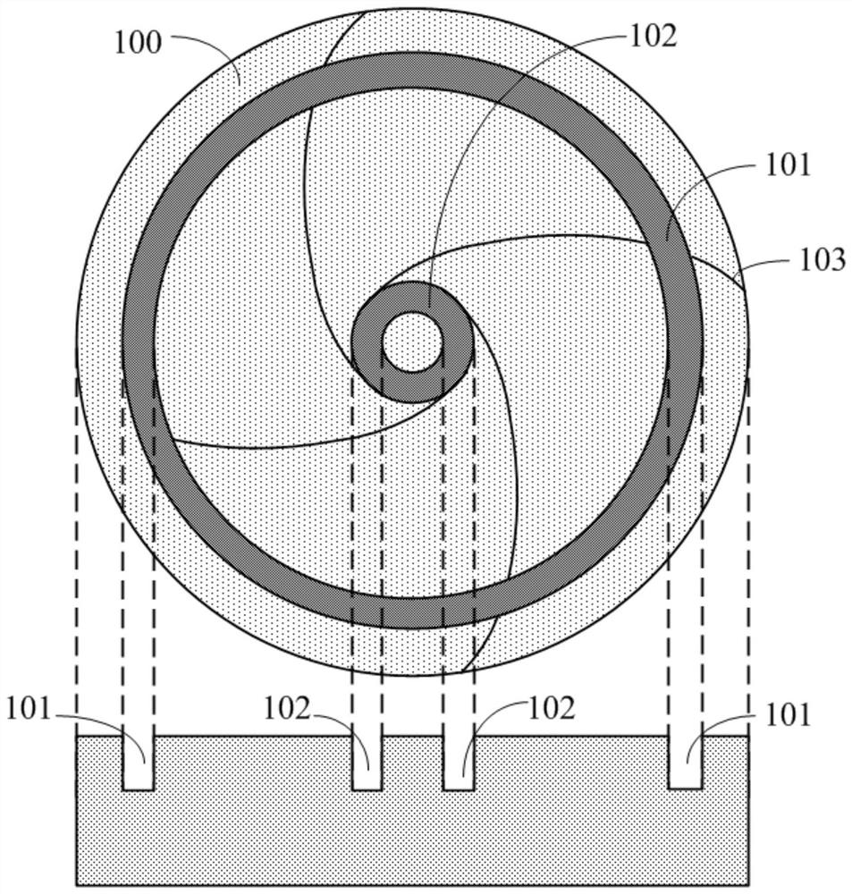
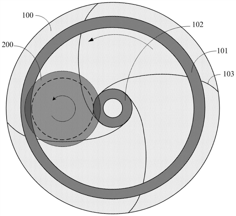
The invention provides a polishing pad, polishing equipment and a polishing method of a silicon wafer. The polishing pad comprises a polishing surface in contact with the silicon wafer, the polishingsurface is provided with at least one groove, the grooving positions of the grooves enable the edge of the silicon wafer to be at least partially suspended above the grooves when the silicon wafer ispolished. According to the polishing pad, the polishing equipment and the polishing method of the silicon wafer, only the polishing rate of the edge position of the silicon wafer is reduced under thecondition that the polishing rate of the whole wafer is kept basically unchanged, so that the flatness of the edge thickness of the silicon wafer is improved, and the product yield is increased.

Description

technical field [0001] The invention relates to the technical field of semiconductors, in particular to a polishing pad, polishing equipment and a method for polishing a silicon wafer. Background technique [0002] With the continuous development of IC (Integrated Circuit) technology, the semiconductor industry has higher and higher requirements for silicon wafers. In order to prevent out-of-focus during exposure, the requirements for the flatness of silicon wafers are also becoming more and more stringent. [0003] The surface polishing of silicon wafers often requires two polishing steps: double side polishing (DSP, double side polish) and front final polishing (FP, final polish). Double-side polishing is used to grind the front and back sides of the wafer, and the desired wafer shape can be achieved through the control of the polishing disc, while the final polishing only polishes the front side of the silicon wafer. [0004] For the final polishing process of silicon wa...

Claims


Application Information

Patent Timeline
Patent Type & Authority Applications(China)
IPC IPC(8): B24B29/02B24D13/14
CPCB24B29/02B24D13/14B24B37/042H01L21/02024B24B37/26B24B37/04B24B37/005H01L21/67092H01L21/30625
Inventor 沙酉鹤谢越
Owner ZING SEMICON CORP
Why Eureka
Try Eureka