Parking brake control system, control method and vehicle

A technology of parking brake and control system, applied in the direction of brake safety system, brake, brake components, etc., can solve the problems of rapid mitigation of pneumatic centralized control, affecting train operation safety, reducing train operation safety and rescue efficiency, etc. The effect of ensuring availability and reliability, avoiding hidden dangers of driving, and ensuring train safety

Active Publication Date: 2020-11-17
CRRC QINGDAO SIFANG CO LTD
View PDF9 Cites 5 Cited by
  • Summary
  • Abstract
  • Description
  • Claims
  • Application Information

AI Technical Summary

Problems solved by technology

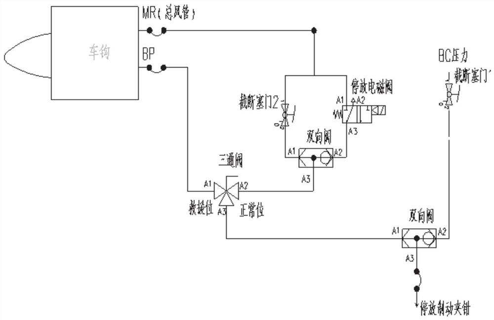
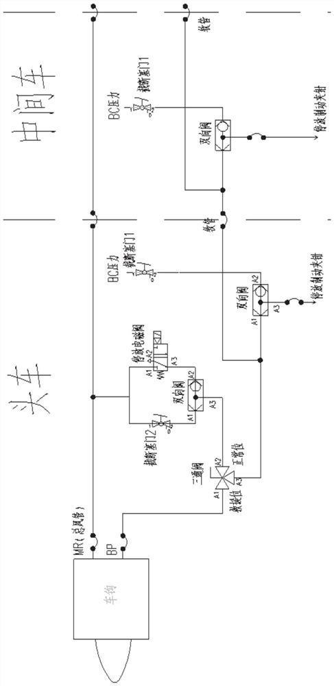
[0003] At present, both rail vehicles and locomotives are equipped with parking brakes. The application and release of parking brakes are controlled by solenoid valves. If the solenoid valve fails, the pneumatic centralized control of parking brakes cannot be quickly relieved, and only manual mechanical isolation can be performed.
At the same time, when an urban rail vehicle is rescued by a locomotive or the same type of urban rail vehicle, the method of isolating all the air brakes is currently used. After the air brake is isolated, the rescued vehicle completely loses its braking force. During the rescue process, only the rescue vehicle can Apply the brakes. In an emergency or when the coupling is uncoupled, the rescued vehicle cannot apply the brakes to stop, which affects the safety of train operation.
[0004] In summary, the inventor found that the current parking brake control system cannot quickly release the parking brake after the parking brake solenoid valve fails, and the rescue process cannot be rescued for a long time due to the influence of the power supply system. It is impossible to control the parking brake to stop, which reduces the safety of train operation and rescue efficiency

Method used


Image

  • Parking brake control system, control method and vehicle
  • Parking brake control system, control method and vehicle

Examples


Embodiment Construction

[0024] The present invention will be further described below in conjunction with the accompanying drawings and embodiments.

[0025] It should be noted that the following detailed description is exemplary and intended to provide further explanation of the present invention. Unless defined otherwise, all technical and scientific terms used herein have the same meaning as commonly understood by one of ordinary skill in the art to which this invention belongs.

[0026] It should be noted that the terminology used here is only for describing specific embodiments, and is not intended to limit exemplary embodiments according to the present invention. As used herein, unless the context clearly dictates otherwise, the singular is intended to include the plural, and it should also be understood that when the terms "comprising" and / or "comprising" are used in this specification, they mean There are features, steps, operations, means, components and / or combinations thereof.

[0027] In...


PUM


Abstract

The invention belongs to the field of vehicle parking brake control, and provides a parking brake control system, a control method and a vehicle. The parking brake control system comprises a main airpipe, a brake pipe, a first air channel, a second air channel, a third air channel, a cutout cock and a parking electromagnetic valve. The cutout cock and the parking electromagnetic valve are connected in parallel to form a parallel branch air path, the parallel branch air path is connected to the first air path in series, and the first air path is connected with the main air pipe; the second gascircuit is connected with the brake pipe; the third gas circuit is connected with the parking brake clamp; and the third air path can be switched to communicate with the first air path and the secondair path so as to realize parking brake control under the condition of normal operation of the vehicle or vehicle rescue. The parking brake control system is realized purely based on a gas circuit principle, no electric signal control is needed when the vehicle breaks down and is rescued, and the availability and reliability of parking braking of the vehicle under various working conditions are guaranteed.

Description

technical field [0001] The invention belongs to the field of vehicle parking brake control, in particular to a parking brake control system, a control method and a vehicle. Background technique [0002] The statements in this section merely provide background information related to the present invention and do not necessarily constitute prior art. [0003] At present, both rail vehicles and locomotives are equipped with parking brakes. The application and release of parking brakes are controlled by solenoid valves. If the solenoid valve fails, the pneumatic centralized control of parking brakes cannot be quickly released, and only manual mechanical isolation can be performed. At the same time, when an urban rail vehicle is rescued by a locomotive or the same type of urban rail vehicle, the method of isolating all the air brakes is currently used. After the air brake is isolated, the rescued vehicle completely loses its braking force. During the rescue process, only the rescu...

Claims


Application Information

Patent Timeline
Patent Type & Authority Applications(China)
IPC IPC(8): B61H11/10B60T17/00B60T17/18
CPCB60T17/00B60T17/18B61H11/10
Inventor 梁德龙张立明秦嗣峰王有杰王相波
Owner CRRC QINGDAO SIFANG CO LTD
Why Eureka
Try Eureka