Digital high-precision indicator diagram data acquisition device

A technology of data acquisition and dynamometer diagram, applied in the direction of measuring devices, instruments, buildings, etc., can solve the problems that piezoelectric sensors cannot be applied, are easily affected by external interference, and have large load and displacement errors, so as to achieve easy access to objects. Networking, overcoming field temperature difference interference and shock interference, high precision effect

Pending Publication Date: 2020-11-17
SHAANXI KEWO ELECTRIC CO LTD
View PDF0 Cites 3 Cited by
  • Summary
  • Abstract
  • Description
  • Claims
  • Application Information

AI Technical Summary

Problems solved by technology

This type of sensor has the following disadvantages: 1) It is easily affected by external interference, and vibration has a significant impact on piezoelectric sensors, especially in small pressure measurements
2) The influence of temperature is obvious, the sensitivity will decrease with the increase of temperature, and thermal expansion will occur when the temperature rises, resulting in a change of the pre-tightening force of the crystal, so that the output of the sensor will drift
[0006] At present, the most advanced load-displacement integrated machine dynamometer sensor used on oil field pumping units uses piezoelectric ceramic pressure sensors, and its disadvantages are: 1) The principle of displacement measurement is to calculate the pressure of a known object based on F=ma Acceleration, the acceleration is the displacement after the second integration, the measurement of the displacement will have a large error when the stroke frequency of the pumping unit i

Method used


Image

  • Digital high-precision indicator diagram data acquisition device
  • Digital high-precision indicator diagram data acquisition device
  • Digital high-precision indicator diagram data acquisition device

Examples


Embodiment Construction

[0033] In describing the present invention, it is to be understood that the terms "center", "upper", "lower", "front", "rear", "left", "right", "vertical", "horizontal", The orientations or positional relationships indicated by "top", "bottom", "inner", "outer", etc. are based on the orientations or positional relationships shown in the drawings, and are only for the convenience of describing the present invention and simplifying the description, rather than indicating or implying References to devices or elements must have a particular orientation, be constructed, and operate in a particular orientation and therefore should not be construed as limiting the invention. The terms "first" and "second" are used for descriptive purposes only, and cannot be understood as indicating or implying relative importance or implicitly specifying the quantity of indicated technical features. Thus, a feature defined as "first" and "second" may explicitly or implicitly include one or more of t...


PUM


Abstract

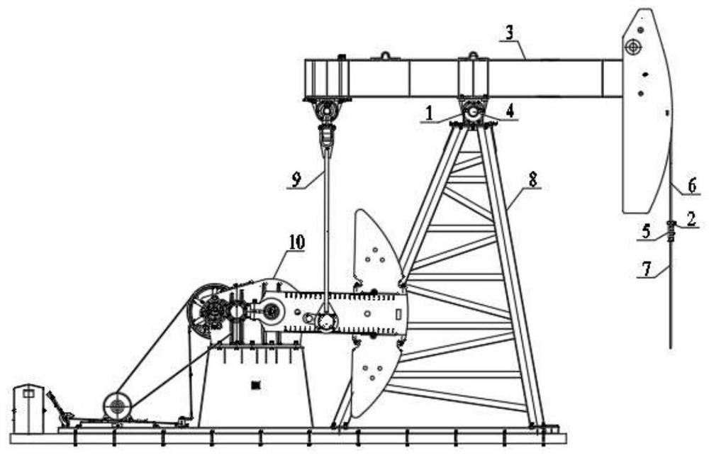
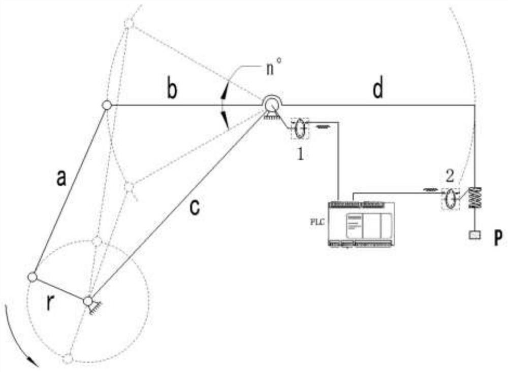
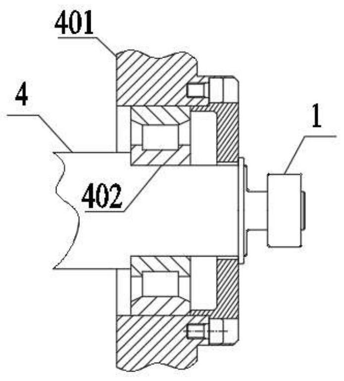
The invention discloses a digital high-precision indicator diagram data acquisition device, and belongs to an electronic indicator diagram technology of an oil field pumping unit in the field of oil production engineering. The device utilizes an angle sensor to obtain a rotation angle of a walking beam, and then utilizes a displacement sensor to obtain relative displacement of a polish rod and a beam hanger; and a processor carries out calculation by using the rotation angle and the pulse number of the relative displacement and completes acquisition of pumping unit indicator diagram data, andan indicator diagram is displayed by a man-machine screen or remotely transmitted to a network to draw the indicator diagram. According to the digital high-precision indicator diagram data acquisitiondevice, a novel indicator diagram data acquisition mode is adopted, aiming at the mechanical structure and the working principle of the beam-pumping unit, the angle sensor is used for acquiring the swing angle of the walking beam and calculating the stroke, the displacement sensor is used for acquiring the displacement data of the polish rod and calculating the load, and the stroke and the load are both direct digital values, outdoor temperature difference interference and impact interference which cannot be overcome by an existing sensor are solved, and the device has the advantages of beinglong in service life, low in cost, high in anti-interference performance and the like.

Description

technical field [0001] The invention belongs to the electronic dynamometer technology of an oil field pumping unit in the field of oil production engineering, and in particular relates to a digital high-precision dynamometer diagram data acquisition device. Background technique [0002] The indicator diagram can reflect the working condition of the deep well pump. It is measured by a special instrument and drawn on the coordinate diagram. The area enclosed by the closed line segment represents the work done by the pumping unit during a reciprocating motion of the donkey head. drawing. Analyzing and explaining the dynamometer diagram is a major means to directly understand the working condition of the deep well pump. Not only can all abnormal phenomena in the work of the deep well pump be reflected intuitively on the dynamometer diagram, but also can be combined with relevant data, To analyze and judge whether the working system of the oil well is reasonable, whether the pum...

Claims


Application Information

Patent Timeline
IPC IPC(8): E21B47/008G01B21/22G01B21/02
CPCG01B21/02G01B21/22
Inventor 何小根王瑜
Owner SHAANXI KEWO ELECTRIC CO LTD
Why Eureka
Try Eureka