
Airtight pump filling device for liquefied gas and used for chemical plant

A technology for liquefied gas and chemical plants, which is applied to the components, pumps, driving pumps, etc. of pumping devices for elastic fluids, which can solve the problem of long equipment preparation time delaying normal production, waste of liquefied gas in pipes, and backflow method requiring exhaust And other issues

Inactive Publication Date: 2020-11-17
苏永芳
View PDF0 Cites 0 Cited by
  • Summary
  • Abstract
  • Description
  • Claims
  • Application Information

AI Technical Summary

Problems solved by technology

[0004] The purpose of the present invention is to provide a kind of liquefied gas sealed filling pump device for chemical plants, to solve the problem that the existing liquefied gas sealed pumping devices for chemical plants often use the backflow filling method, but this backflow filling method The work is slow, the equipment preparation time is too long to delay the normal production, and the backflow method needs exhaust, which wastes a lot of liquefied gas in the pipe

Method used


Image

  • Airtight pump filling device for liquefied gas and used for chemical plant
  • Airtight pump filling device for liquefied gas and used for chemical plant
  • Airtight pump filling device for liquefied gas and used for chemical plant

Examples


Embodiment 1

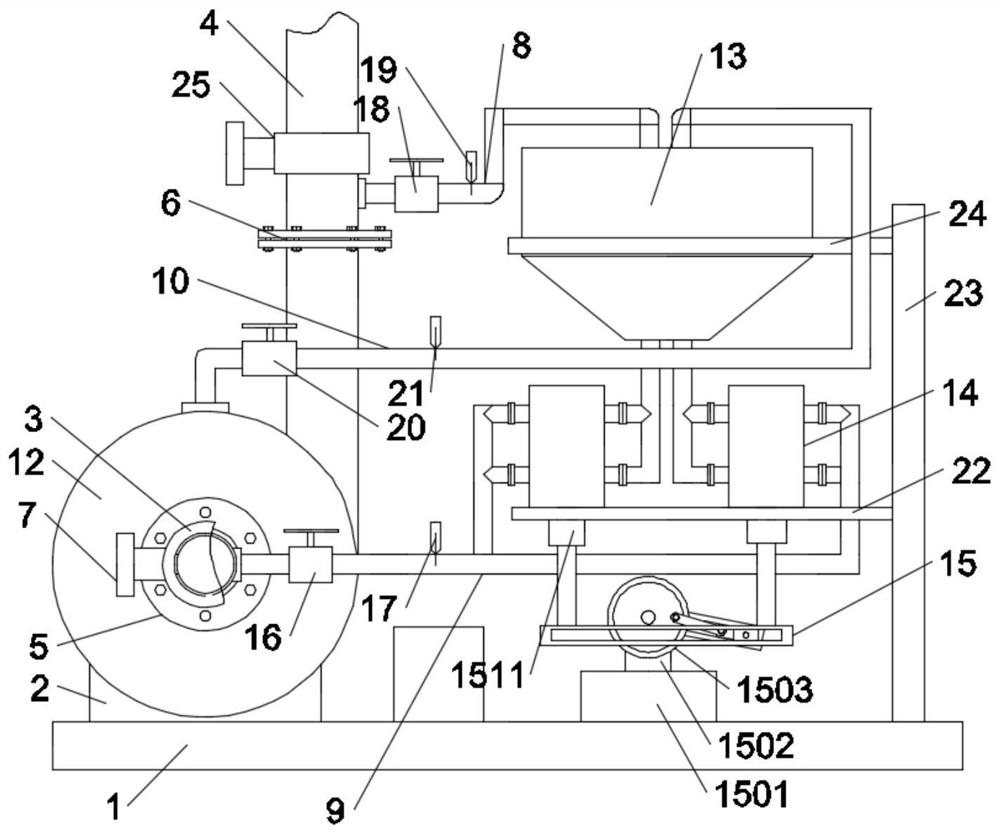
[0022] like figure 1 , figure 2 , image 3 and Figure 4 As shown, in the embodiment of the present invention, a liquefied gas sealed filling pump device for a chemical plant includes a mounting base 1, a first motor mounting base 2 is connected to the mounting base 1, and the first motor mounting base 2 A first motor 11 is installed on it, and the first motor 11 is connected with a pump body 12, and the pump body 12 is connected with a water suction pipe 3 and a water outlet pipe 4, and the water suction pipe 3 and the water outlet pipe 4 are respectively connected with first The flange connection port 5 and the second flange connection port 6, the suction pipe 3 and the water outlet pipe 4 are respectively equipped with a first solenoid valve 7 and a second solenoid valve 25, which are located at the first flange connection port 5 and the second flange connection port. The outlet pipe 4 between the electromagnetic valves 7 is connected with the first air delivery pipe 8,...

Embodiment 2

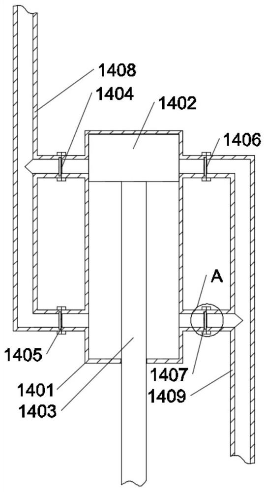
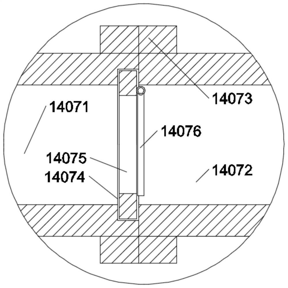
[0025] like figure 1 , figure 2 , image 3 and Figure 4 As shown, in the embodiment of the present invention, the pumping device 14 on the right side includes a hydraulic cylinder 1401, a piston 1402 is arranged inside the hydraulic cylinder 1401, and a pumping rod 1403 is connected to the piston 1402, which is located in the hydraulic cylinder 1401. A first one-way pipe valve 1404 and a second one-way pipe valve 1405 are respectively connected up and down on the left side of the cylinder 1401, and a third one-way pipe valve 1406 and a fourth one-way pipe valve 1407 are respectively connected above and below the hydraulic cylinder 1401. The first one-way pipe valve 1404 and the second one-way pipe valve 1405 communicate with a first pipe 1408, the first pipe 1408 is connected to the bottom of the storage tank 13 for barrel-shaped irrigation pump, and the third one-way pipe valve 1406 and the fourth one-way valve 1407 communicate with a second pipeline 1409 , and the secon...

Embodiment 3

[0028] like figure 1 , figure 2 , image 3 and Figure 4As shown, in the embodiment of the present invention, a third solenoid valve 16 is connected to the pipeline near the suction pipe 3 of the infusion tube 9, and a first pressure sensor 17 is also provided on the infusion tube 9, which is located on the first pressure sensor 17. A fourth solenoid valve 18 is connected to the pipeline near the position of the water outlet pipe 4 of an air delivery pipe 8, and a second pressure sensor 19 is connected to the first air delivery pipe 8 on the right side of the fourth solenoid valve 18, located at the second delivery pipe 8. A fifth solenoid valve 20 is connected to the gas pipe 10 near the pump body 12 , and a third pressure sensor 21 is connected to the second gas delivery pipe 10 on the right side of the fifth solenoid valve 20 .

[0029] In the embodiment of the present invention, when the pressure values ​​of the first pressure sensor 17, the second pressure sensor 19 a...


PUM


Abstract

The invention relates to the technical field of airtight pump filling for liquefied gas and used for chemical plants, and specifically relates to an airtight pump filling device for liquefied gas andused for a chemical plant. The airtight pump filling device for liquefied gas and used for the chemical plant comprises an installation bottom plate, wherein a first motor installation seat is connected to the installation bottom plate; a first motor is installed on the first motor installation seat; a pump body is connected to the first motor; the pump body is connected with a water pumping pipeand a water outlet pipe; the water pumping pipe and the water outlet pipe are connected with a first flange connecting port and a second flange connecting port separately; the upper end of the pump body is connected with a second gas conveying pipe; the second gas conveying pipe and the first gas conveying pipe are connected with a barrel-shaped storage tank for pump filling and with a conical bottom; the bottom end of the barrel-shaped storage tank for pump filling and with the conical bottom is symmetrically connected with two liquid pumping devices; and the lower ends of the liquid pumpingdevices are connected with driving devices. A gas pumping suction method is adopted in the device, and the filling method is high in working efficiency, short in equipment preparation time, and free from delay on normal production; and moreover, gas exhaust is not needed, so that waste for the liquefied gas in a pipe can be avoided.

Description

technical field [0001] The invention relates to the technical field of a liquefied gas sealed filling pump for a chemical plant, in particular to a liquefied gas sealed filling pump device for a chemical plant. Background technique [0002] Before the centrifugal pump is started, the suction pipe, impeller and pump casing must be filled with the delivered liquid. This operation is called priming the pump. Depending on the liquid to be transported and the working conditions of the equipment, there are mainly several methods for filling the pump: tap water filling method, reverse flow filling method, downstream filling method and suction suction method. For liquefied petroleum gas, the latter three methods are more appropriate. [0003] The working mode of the existing liquefied gas sealed filling pump devices in chemical plants is mostly the backflow filling method, but this backflow filling method works slowly, and the equipment preparation time is too long to delay normal ...

Claims


Application Information

Patent Timeline
IPC IPC(8): F04D9/00F04D29/00
CPCF04D9/00F04D29/007
Inventor 苏永芳
Owner 苏永芳
Learn More