Natural gas conveying anti-explosion metal hose
A technology for metal hoses and natural gas pipes, applied in the direction of hoses, pipes/pipe joints/fittings, pipes, etc., can solve the problems of low strength and high flow rate of metal hoses, achieve frictional static suppression, prolong service life, reduce Effect of Minor Accident Rate
- Summary
- Abstract
- Description
- Claims
- Application Information
AI Technical Summary
Problems solved by technology
Method used
Image

Examples
Embodiment 1
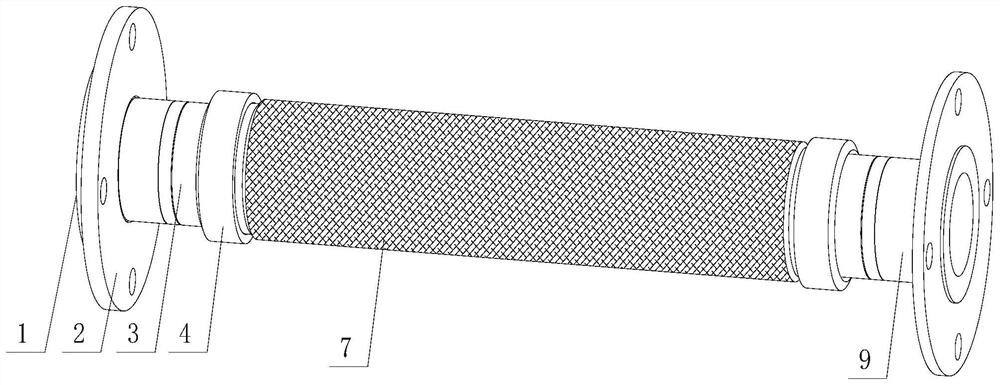
[0033] Such as Figure 1-9 The shown explosion-proof metal hose for natural gas pipelines aims to solve the problems of static sparks and static flash explosions caused by friction with the nozzle due to the high flow rate of natural gas leakage. In order to solve the above problems, this device uses different steel belts 7 design. The specific installation is as follows:
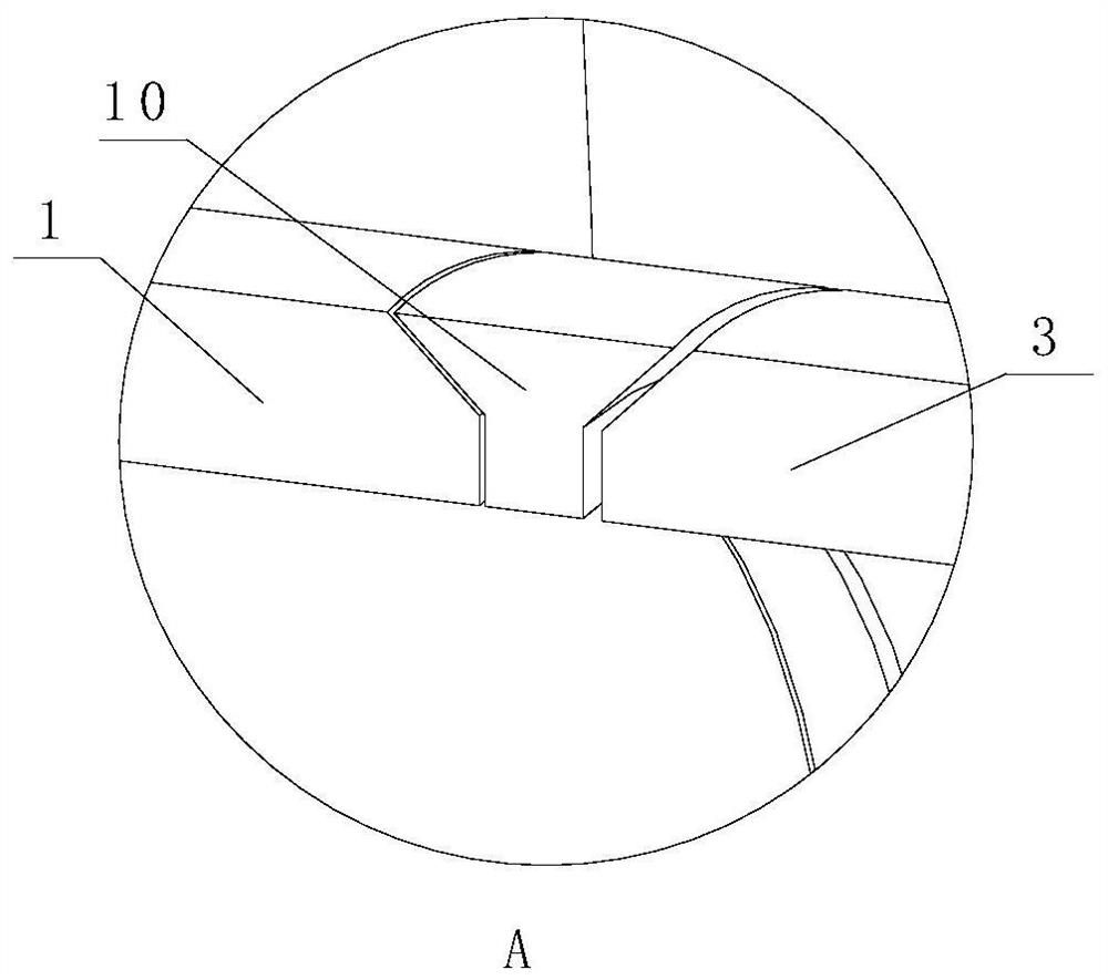
[0034] Such as figure 1 and figure 2 As shown, the device takes a metal hose 5 as a base, and a steel belt 7 is wrapped on the outer surface of the metal hose 5 . At the two ends of the metal hose 5, a cylindrical metal nipple 3 is installed. In order to make the contact between the metal nipple 3 and the metal hose 5 stable, an end ring 8 is set between the metal nipple 3 and the metal hose 5, such as Figure 5 shown.
[0035] In order to keep the metal pup joint 3, the metal hose 5 and the steel strip 7 stable, the compression ring 4 structure is selected. Installation structure such as image 3 ...
Embodiment 2
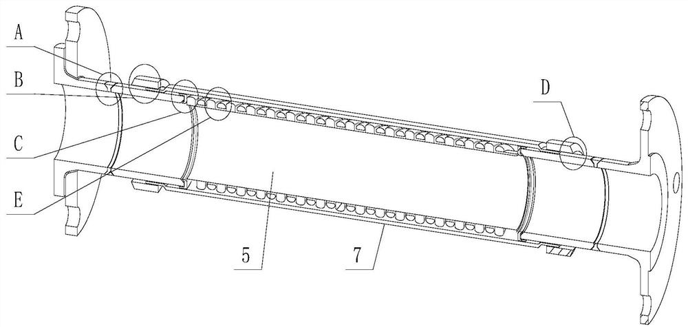
[0040] Such as Figure 1-9 The shown explosion-proof metal hose for natural gas pipelines aims to solve the problem that the ordinary metal hose has a low strength and weak high-pressure resistance, which makes the metal hose have a tendency to burst and leak. In order to solve the above problems, this device adopts the additional design of the reinforcement ring 6. The specific installation is as follows:
[0041] Such as Figure 1-9 The shown explosion-proof metal hose for natural gas pipelines aims to solve the problems of static sparks and static flash explosions caused by friction with the nozzle due to the high flow rate of natural gas leakage. In order to solve the above problems, this device uses different steel belts 7 design. The specific installation is as follows:
[0042] Such as figure 1 and figure 2 As shown, the device takes a metal hose 5 as a base, and a steel belt 7 is wrapped on the outer surface of the metal hose 5 . At the two ends of the metal ho...
PUM
 Abstract
Description
Claims
Application Information