Electrolyte conveying device for microelectronic processing

A transportation device and electrolyte technology, which is applied in the manufacture of circuits, electrical components, semiconductors/solid-state devices, etc., can solve the problems of affecting the microelectronics processing process, affecting the fluid flow rate, and transporting more electrolytes, so as to facilitate subsequent processing and use, Ensure normal operation and improve transportation efficiency

Pending Publication Date: 2020-11-17
朱言文
View PDF0 Cites 0 Cited by
  • Summary
  • Abstract
  • Description
  • Claims
  • Application Information

AI Technical Summary

Problems solved by technology

[0004] The purpose of the present invention is to solve the shortcomings in the prior art, such as: in the traditional electrolyte transportation process, the shear force between the pipe wall and the fluid will affect the flow rate of the fluid, greatly reducing the transportation efficiency, and the interruption of transportation is prone to delay Leading to excessive delivery of electrolyte, affecting the microelectronics processing process, and a proposed electrolyte transport device for microelectronics processing

Method used


Image

  • Electrolyte conveying device for microelectronic processing
  • Electrolyte conveying device for microelectronic processing
  • Electrolyte conveying device for microelectronic processing

Examples


Embodiment 1

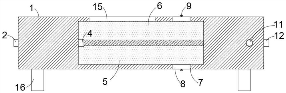
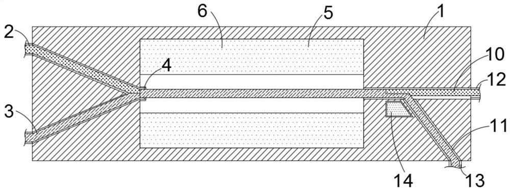
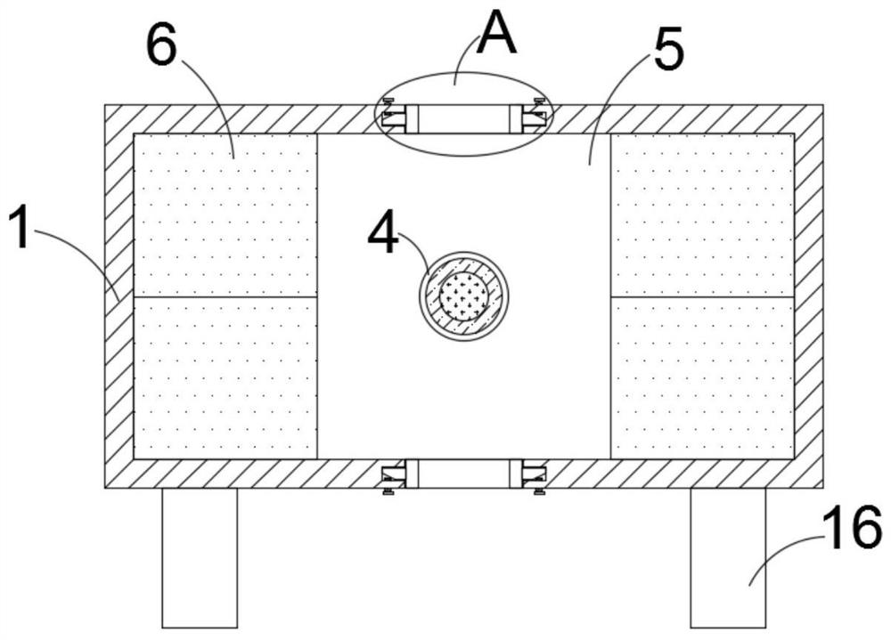
[0022] refer to Figure 1-4 , an electrolyte transportation device for microelectronics processing, comprising a casing 1, a transportation cavity 5 is opened in the casing 1, an infusion channel 3 is arranged in the casing 1, and the infusion channel 3 is arranged in a V shape in the transportation cavity 5, two liquid inlets 2 are fixedly arranged on the side wall of the housing 1, and the two liquid inlets 2 are connected with one end of the infusion channel 3, and the transport chamber 5 is close to the side of the infusion channel 3 A converging port 4 is fixedly arranged on the side wall, and the converging port 4 is connected with the end of the infusion channel 3 away from the liquid inlet 2. The transport chamber 5 is fixedly provided with two sets of magnet strips 6, and the two sets of magnet bars 6 are symmetrically arranged at the converging port. 4, and each group of magnet strips 6 includes two magnet strips 6 stacked together. The liquid channel 10, the liquid...

Embodiment 2

[0026] refer to Figure 5 The difference between this embodiment and Embodiment 1 is that two cut-off magnetic blocks 19 are added, that is, two clamping openings 7, two clamping openings 7, and two clamping openings are opened on the side walls on both sides of the housing 1. Two clamping plates 8 are slidingly arranged inside the mouth 7, and a pushing mechanism corresponding to the clamping plates 8 is provided on the housing 1. The pushing mechanism includes four bolts 9, and two side walls on both sides of the clamping mouth 7 Two telescopic slots 18 are symmetrically opened on the top, and a push plate 17 is fixedly arranged on the side wall of each clamping plate 8 close to the telescopic slot 18, and four push plates 17 are respectively slidably arranged in the four telescopic slots 18. , four bolts 9 respectively penetrate through the two side walls of the housing 1 and communicate with the four telescopic grooves 18, and the two side walls of the housing 1 are provid...


PUM


Abstract

The electrolyte conveying device for microelectronic processing comprises a shell, a conveying cavity is formed in the shell, a liquid conveying channel is formed in the shell, the liquid conveying channel is arranged on one side of the conveying cavity in a V shape, two liquid inlets are fixedly formed in the side wall of one side of the shell. The two liquid inlets are correspondingly communicated with one end of the liquid conveying channel, a converging opening is fixedly formed in the side wall of the side, close to the liquid conveying channel, of the conveying cavity, and the convergingopening is correspondingly communicated with the end, away from the liquid inlets, of the liquid conveying channel. Magnetic liquid with a stable quadrupole magnetic field is used as a liquid pipe wall, and a water-based microfluid channel is constructed; that is to say, the water-based microfluid flows under the surrounding of the immiscible magnetic liquid, so that the interaction between the fluid and the pipe wall is greatly reduced, almost no friction exists, the liquid pipe wall can be self-cured, no blocking risk exists, and the valve opening and closing control function can be conveniently achieved.

Description

technical field [0001] The invention relates to the technical field of microelectronic processing, in particular to an electrolyte transport device for microelectronic processing. Background technique [0002] Microelectronics technology is a discipline that acts on micro-miniature integrated circuit systems on semiconductors. The key to microelectronics technology lies in the study of the working mode of integrated circuits and how to actually manufacture and apply them. With the continuous development of the times, the microelectronics processing industry has also gained In the process of microelectronics processing, it is often necessary to use microchannels to transport electrolyte. [0003] However, in the prior art, during the transportation of the electrolyte, the flow rate of the fluid is often affected by the shear force between the pipe wall and the fluid between the channels, and the air bubbles or impurities in the electrolyte are often The blockage of the micro...

Claims


Application Information

Patent Timeline
Patent Type & Authority Applications(China)
IPC IPC(8): H01L21/67
CPCH01L21/67011H01L21/67017
Inventor 朱言文
Owner 朱言文
Why Eureka
Try Eureka