Supercharge Your Innovation With Domain-Expert AI Agents!

Depth detection assembly and electronic equipment

A technology for depth detection and electronic equipment, which is applied to TVs, electrical components, color TVs, etc. It can solve the problems of depth imaging pixel offset and affect depth imaging accuracy, and achieve the effect of reducing pixel offset and improving accuracy.

Active Publication Date: 2020-11-17
GUANGDONG OPPO MOBILE TELECOMM CORP LTD
View PDF10 Cites 1 Cited by
  • Summary
  • Abstract
  • Description
  • Claims
  • Application Information

AI Technical Summary

Problems solved by technology

[0003] When the distance between the object to be photographed and the emitter module is different, the light emitted by the transmitter module is reflected at different positions on the receiver module, resulting in a change in the spatial position of the object to be photographed at different depths, that is, there are pixels in depth imaging. The problem of offset affects the accuracy of depth imaging

Method used

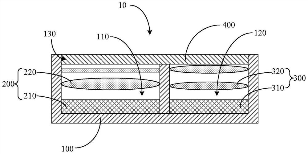
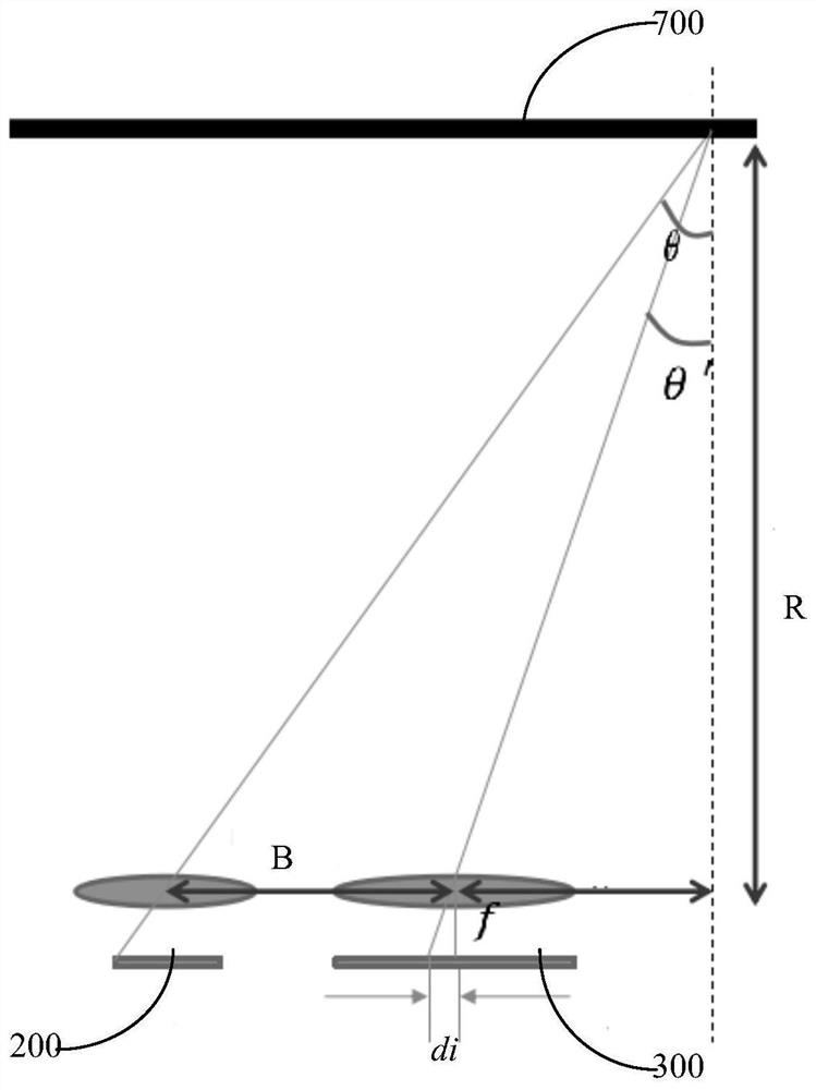
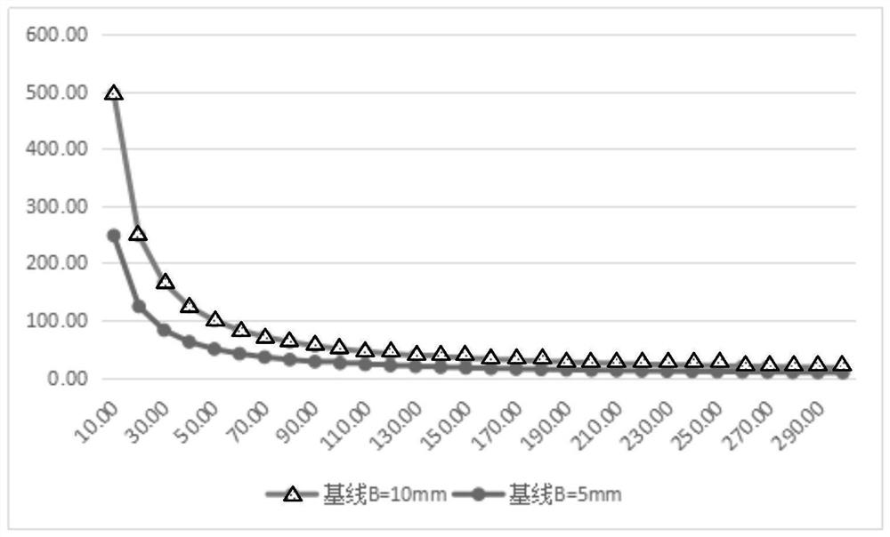

Image

  • Depth detection assembly and electronic equipment
  • Depth detection assembly and electronic equipment
  • Depth detection assembly and electronic equipment

Examples


Embodiment Construction

[0023] Example embodiments will now be described more fully with reference to the accompanying drawings. Example embodiments may, however, be embodied in many forms and should not be construed as limited to the embodiments set forth herein; rather, these embodiments are provided so that this disclosure will be thorough and complete, and will fully convey the concept of example embodiments to those skilled in the art. The same reference numerals in the drawings denote the same or similar structures, and thus their detailed descriptions will be omitted.

[0024] Although relative terms such as "upper" and "lower" are used in this specification to describe the relative relationship of one component of an icon to another component, these terms are used in this specification only for convenience, for example, according to the description in the accompanying drawings directions for the example described above. It will be appreciated that if the illustrated device is turned over so...


PUM


Abstract

The invention relates to the technical field of electronic equipment, in particular to a depth detection assembly and electronic equipment. The depth detection assembly comprises a transmitting module, a receiving module and a support. The transmitting module is used for transmitting initial light waves; the receiving module is used for receiving reflected light waves; and a first mounting part and a second mounting part are integrated on the support, the transmitting module is arranged on the first mounting part, the receiving module is arranged on the second mounting part, and the first mounting part and the second mounting part are configured to enable the receiving module to receive the reflected light waves. The reflected light waves are the initial light waves reflected by a shootingtarget object, and the precision of depth imaging can be improved.

Description

technical field [0001] The present disclosure relates to the technical field of electronic equipment, in particular, to a depth detection component and electronic equipment. Background technique [0002] In TOF (Time of Flight) technology, the transmitting module emits near-infrared light, and the near-infrared light is reflected to the receiving module after encountering the object to be photographed, and the time difference or phase difference between light emission and reflection is calculated to obtain Capture the distance of the scene to generate depth information. [0003] When the distance between the object to be photographed and the emission module is different, the light emitted by the transmitting module is reflected at different positions on the receiving module, resulting in changes in the spatial position of the object to be photographed at different depths, that is, there are pixels in depth imaging. The problem of offset affects the accuracy of depth imaging...

Claims


Application Information

Patent Timeline
IPC IPC(8): H04N5/225
CPCH04N23/57H04N23/55
Inventor 张学勇
Owner GUANGDONG OPPO MOBILE TELECOMM CORP LTD
Features
  • R&D
  • Intellectual Property
  • Life Sciences
  • Materials
  • Tech Scout
  • Unparalleled Data Quality
  • Higher Quality Content
  • 60% Fewer Hallucinations
Learn More