Steel casting protection device

A protection device, steel technology, used in casting melt containers, metal processing equipment, casting equipment, etc.

Inactive Publication Date: 2020-11-20
徐子敏
View PDF10 Cites 2 Cited by
  • Summary
  • Abstract
  • Description
  • Claims
  • Application Information

AI Technical Summary

Problems solved by technology

[0004] The purpose of the present invention is to provide a steel pouring protection device in order to solve the above problems. The present invention is provided with a feeding mechanism and a rotating mechanism, and by placing the storage box on the rotating mechanism, thereby starting the feeding mechanism. The No. 1 motor drives the threaded rod to rotate, thereby driving the sliders at both ends to move up through the threaded sleeve plate, thereby driving the entire rotating mechanism to move up. This design, compared with the traditional manual handling for pouring, can avoid manual The pouring liquid that occurs during the handling process is spilled, thereby causing pollution to the staff and the surrounding environment. The present invention is provided with a material storage mechanism, and the cover plate and threaded end of the material storage mechanism can prevent the material storage box from moving to the placement plate. If the pouring liquid spills out, the power mechanism is installed, and the No. 2 motor in the power mechanism drives the screw blade to rotate, so that the outside air is sucked into the exhaust shell, so that the internal pressure of the material storage box under the pusher plate Increase, and then push the pusher plate to move up, so as to push the pouring liquid in the material storage box upwards. At this time, only need to open the No. 1 electric control valve to make the pouring liquid flow out and fall into the casting mold. With this design, there is no need for manual pouring when pouring the pouring liquid, and it can be operated remotely, avoiding the injury to the staff when the pouring mold is broken, and the flow of the pouring liquid can be controlled by opening and closing the No. 1 electric control valve

Method used


Image

  • Steel casting protection device
  • Steel casting protection device
  • Steel casting protection device

Examples


Embodiment Construction

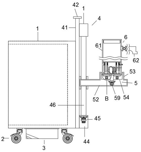
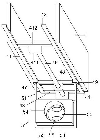
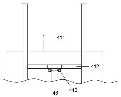
[0036] Such as Figure 1-9 As shown, this specific embodiment adopts the following technical solutions: a steel pouring protection device, including a protective plate 1 and a universal wheel 2, the design of the protective plate 1 can protect the mold, and avoid pouring due to the problems of the mold itself. failure, the shape of the protective plate 1 is C-shaped, two universal wheels 2 are installed on the bottom of the protective plate 1, and the bottom of the protective plate 1 between the universal wheels 2 is provided with an anti-dumping mechanism 3, and the protective plate 1 side is equipped with a feeding mechanism 4, the feeding mechanism 4 is provided with a rotating mechanism 5, the rotating mechanism 5 is provided with a storage mechanism 6, and a buffer mechanism 7 is arranged in the storage mechanism 6, and the storage mechanism 7 between the buffer mechanisms A power mechanism 8 is arranged inside the material mechanism 6 , and an auxiliary mechanism 9 is ar...


PUM


Abstract

The invention discloses a steel casting protection device which comprises a protection plate and universal wheels. The protection plate is of a C shape. The two universal wheels are disposed at the bottom of the protection plate. An anti-tilt mechanism is disposed at the bottom of the portion, between the universal wheels, of the protection plate. A feeding mechanism is disposed on one side of theprotection plate. A rotating mechanism is disposed on the feeding mechanism. A storing mechanism is disposed on the rotating mechanism. A buffering mechanism is disposed in the storing mechanism. Thesteel casting protection device has the beneficial effects that the feeding mechanism and the rotating mechanism are disposed, a storing box is placed on the rotating mechanism, a first motor in thefeeding mechanism is started, a threaded rod is driven to rotate, sliders at the two ends of the threaded rod are driven by a threaded sleeve plate to move upwards, and thus the whole rotating mechanism is driven to move upwards; and due to the design, compared with traditional manual carrying for casting, it can be avoided that a casting solution is splashed out in the manual carrying process, result in causing contamination to workers and surrounding environment.

Description

Technical field: [0001] The invention belongs to the technical field of iron and steel production, in particular to a protective device for pouring iron and steel. Background technique: [0002] Pouring process refers to the method and technology of pouring molten steel into ingots. The pouring method can be divided into upper betting and lower betting according to the position where molten steel enters the ingot mold. The steel types such as stainless steel, silicon steel, and thin plate with strict surface quality requirements use lower betting, and the steel types such as heavy rails and gun barrels with high internal quality requirements are many. Up betting is adopted; small ingots can only be placed, while large ingots are suitable for up betting. [0003] In the prior art, in the iron and steel production process, most of the pouring liquid is poured into the mold by manual handling, so as to complete the casting of steel. However, during the pouring process of the p...

Claims


Application Information

Patent Timeline
Patent Type & Authority Applications(China)
IPC IPC(8): B22D41/06B22D41/12
CPCB22D41/06B22D41/12
Inventor 徐子敏
Owner 徐子敏
Why Eureka
Try Eureka