Data acquisition system of turboshaft engine double-channel electronic control system

A technology of electronic control system and data acquisition system, which is applied in the direction of engine control, machine/engine, mechanical equipment, etc. It can solve the problems of low system reliability, failure of control channel, and inability to control the channel, so as to facilitate system expansion and circuit Effects with low complexity

Pending Publication Date: 2020-11-20
四川海特亚美航空技术有限公司
View PDF9 Cites 0 Cited by
  • Summary
  • Abstract
  • Description
  • Claims
  • Application Information

AI Technical Summary

Problems solved by technology

[0003] At present, the data acquisition of the dual-channel electronic control system of the turboshaft engine generally adopts the technical scheme of direct acquisition; the dual-channel electronic control system of the turboshaft engine is mainly composed of an electronic controller, sensors, actuators and cables. A control channel directly collects the sensor output signal in the corresponding channel, and controls the corresponding actuator of the chann

Method used


Image

  • Data acquisition system of turboshaft engine double-channel electronic control system
  • Data acquisition system of turboshaft engine double-channel electronic control system

Examples


Embodiment 1

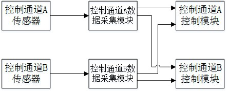
[0027] A data acquisition system for a dual-channel electronic control system of a turboshaft engine, such as figure 1 , including control channel A sensor, control channel B sensor, control channel A data acquisition module, control channel B data acquisition module, control channel A control module and control channel B control module, wherein:

[0028] The control channel A sensor is connected to the control channel A data acquisition module, and the control channel B sensor is connected to the control channel B data acquisition module;

[0029] The control channel A data acquisition module is connected to the control channel A control module and the control channel B control module respectively, and the control channel B data acquisition module is respectively connected to the control channel A control module and the control channel B control module.

[0030] Working principle: In the technical solution of the present invention, the SPI bus is used to connect the control c...

Embodiment 2

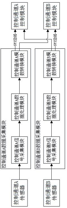
[0033] In this embodiment, on the basis of Embodiment 1, the control module of the control channel A and the control module of the control channel B use a CPU to read and process data.

[0034] Such as figure 2 , the connection mode between the control channel A data acquisition module, the control channel A control module and the control channel B control module is the SPI bus connection mode. The connection mode between the control channel B data acquisition module, the control channel A control module and the control channel B control module is the SPI bus connection mode.

[0035] The control channel A data acquisition module and the control channel B data acquisition module both include a signal acquisition module and an analog-to-digital conversion module; in the data acquisition module of the same control channel, the signal acquisition module and the analog-to-digital conversion module are connected; the control channel The signal acquisition module in the A data acq...


PUM


Abstract

A data acquisition system of a turboshaft engine double-channel electronic control system is based on a control channel A and a control channel B of the turboshaft engine double-channel electronic control system and comprises a control channel A sensor, a control channel B sensor, a control channel A data acquisition module, a control channel B data acquisition module, a control channel A controlmodule and a control channel B control module. The control channel A sensor is connected to the control channel A data acquisition module. The control channel B sensor is connected to the control channel B data acquisition module. The control channel A data acquisition module is connected with the control channel A control module and the control channel B control module. The control channel B dataacquisition module is connected with the control channel A control module and the control channel B control module. In this way, the control channel A control module and the control channel B controlmodule both can collect the signals of the sensors corresponding to the control channel A and the control channel B, and redundancy design of output signals of the sensors is achieved.

Description

technical field [0001] The invention relates to the field of turboshaft engines, in particular to a data acquisition system for a dual-channel electronic control system of a turboshaft engine. Background technique [0002] The full name of the turboshaft engine is an aviation turboshaft engine (turboshaft engine), which is a turbojet engine that outputs shaft power. Since the flying speed of the helicopter is not high, generally the maximum level flight speed is below 350km / h, so the inflow inlet of the air intake device adopts a convergent shape, so that the airflow can accelerate the flow in the convergent inlet to improve the flow field of the airflow. unevenness. The inlet lip of the air intake device is smooth and streamlined, which is suitable for subsonic streamline requirements, so as to avoid the sudden direction turning of the air flow at the inlet, causing air flow separation, and creating a good air intake environment for the stable operation of the compressor. ...

Claims


Application Information

Patent Timeline
IPC IPC(8): F02C9/00
CPCF02C9/00F05D2270/54
Inventor 甘祥杨东杜明
Owner 四川海特亚美航空技术有限公司
Why Eureka
Try Eureka