Testing device and testing equipment

A testing device and cylinder technology, applied in geophysical measurement, seismology for logging records, instruments, etc., can solve the problem of difficulty in proposing reflection arrival time and reflection sound amplitude, difficulty in judging the reliability of ultrasonic probes, and inability to judge the reliability of ultrasonic probes. The reliability of instrument imaging and other issues have achieved the effect of simple structure, convenient debugging and operation, and small workload.

Pending Publication Date: 2020-11-20
CHINA NAT OFFSHORE OIL CORP +1
View PDF19 Cites 0 Cited by
  • Summary
  • Abstract
  • Description
  • Claims
  • Application Information

AI Technical Summary

Problems solved by technology

This method of judging the working performance of the instrument on site will cause two problems: First, since the acoustic window is exposed to the air during instrument debugging, there is no effective reflection interface, and accurate reflection waveforms cannot be obtained, and it is difficult to propose the reflection arrival time and Reflecting the sound amplitude, it is difficult to judge the reliability of the ultrasonic probe; second, the acoustic imaging is a 360-degree full-hole scan image of the well wall, and the on-site instrument performance test method is difficult to simulate the downhole logging environment because the instrument is exposed to the air. Therefore, the reliability of the instrument imaging cannot be judged

Method used


Image

  • Testing device and testing equipment
  • Testing device and testing equipment
  • Testing device and testing equipment

Examples


Embodiment Construction

[0014] Hereinafter, the embodiments of the present invention will be described with reference to the accompanying drawings. It should be noted that, in the case of no conflict, the embodiments of the present invention and the features in the embodiments can be combined with each other arbitrarily.

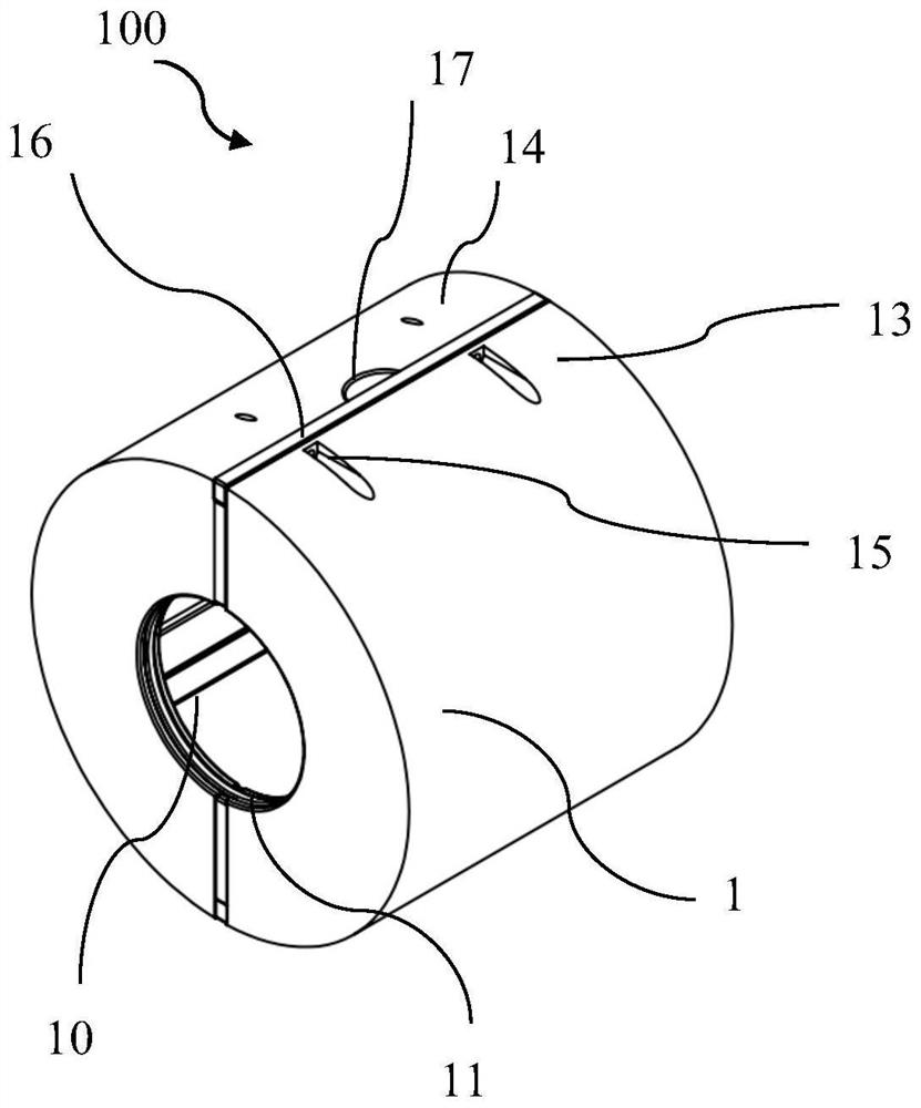
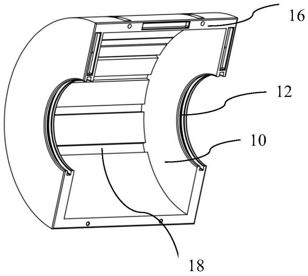
[0015] Such as Figure 1-5 As shown, the embodiment of the present invention provides a testing device 100, which includes a cylinder 1 and an inner cavity 10 provided in the cylinder 1. Both ends of the cylinder 1 are respectively provided with perforations 11 and 12 communicating with the inner cavity 10. The cylinder 1 is arranged to be able to be installed at the acoustic window position of the acoustic imaging instrument 200 around the well. The perforations 11 and 12 are configured to allow the sound system short 2 of the acoustic imaging instrument 200 to penetrate. The barrel 1 of the embodiment of the present invention is made of aluminum alloy.

[0016] The embodiment of t...


PUM


Abstract

The embodiment of the invention discloses a testing device and testing equipment, the testing device comprises a cylinder body and an inner cavity arranged in the cylinder body, and the two ends of the cylinder body are respectively provided with a through hole communicated with the inner cavity; the cylinder body is arranged to be capable of being installed at the position of an acoustic window of a periodontal acoustic imaging instrument, and the through hole is arranged to be capable of allowing an acoustic system short circuit of the periodontal acoustic imaging instrument to penetrate through.

Description

Technical field [0001] The embodiments of the present invention relate to, but are not limited to, offshore operation equipment, and more specifically, to a testing device and testing equipment. Background technique [0002] The perimeter acoustic imaging logging tool is used for ultrasonic scanning of the borehole wall of an open hole or a cased hole to generate detailed images. The probe of the instrument emits high-frequency acoustic pulses and measures the arrival time and amplitude of the borehole echo. The amplitude of the echo is affected by the structure of the borehole wall, and then reflects the distance between the probe and the borehole wall. The ultrasonic probe is installed in the rotating part of the instrument, so that it can scan the borehole wall 360° around the well and generate two sets of images: amplitude and time. [0003] At present, the performance test method of acoustic imaging instruments is carried out in scaled wells. There is no test environment of ...

Claims


Application Information

Patent Timeline
Patent Type & Authority Applications(China)
IPC IPC(8): G01V13/00G01V1/40
CPCG01V13/00G01V1/40
Inventor 郭尚静彭凯旋李辉张利伟李苏赵龙
Owner CHINA NAT OFFSHORE OIL CORP
Why Eureka
Try Eureka