Rubber tapping machine and rubber tapping method

A rubber tapping machine and rubber tapping technology, applied in forestry, application, agriculture, etc., can solve the problems of thickness adjustment, laborious tapping, poor effect, etc., to achieve uniform cutting depth, improve practicability, and improve stability.

Pending Publication Date: 2020-11-24
NINGBO CIHEVEA TECH CO LTD
View PDF11 Cites 12 Cited by
  • Summary
  • Abstract
  • Description
  • Claims
  • Application Information

AI Technical Summary

Problems solved by technology

The shape of the ring planetary gear shell of this rubber tapping machine is fixed and cannot be adjusted according to the thickness of the rubber trunk. If the rubber trunk is thin, the force arm between the rubber tapping knife assembly and the rubber trunk is longer, and the rubber tapping is laborious and the effect is poor. The tool holder adopts the transmission method of gear and rack, which has a high failure rate and troublesome installation; in addition, the position of the cutter head of this rubber tapping machine is fixed, while the surface of the rubber bark is irregular. This

Method used


Image

  • Rubber tapping machine and rubber tapping method
  • Rubber tapping machine and rubber tapping method
  • Rubber tapping machine and rubber tapping method

Examples


Embodiment 1

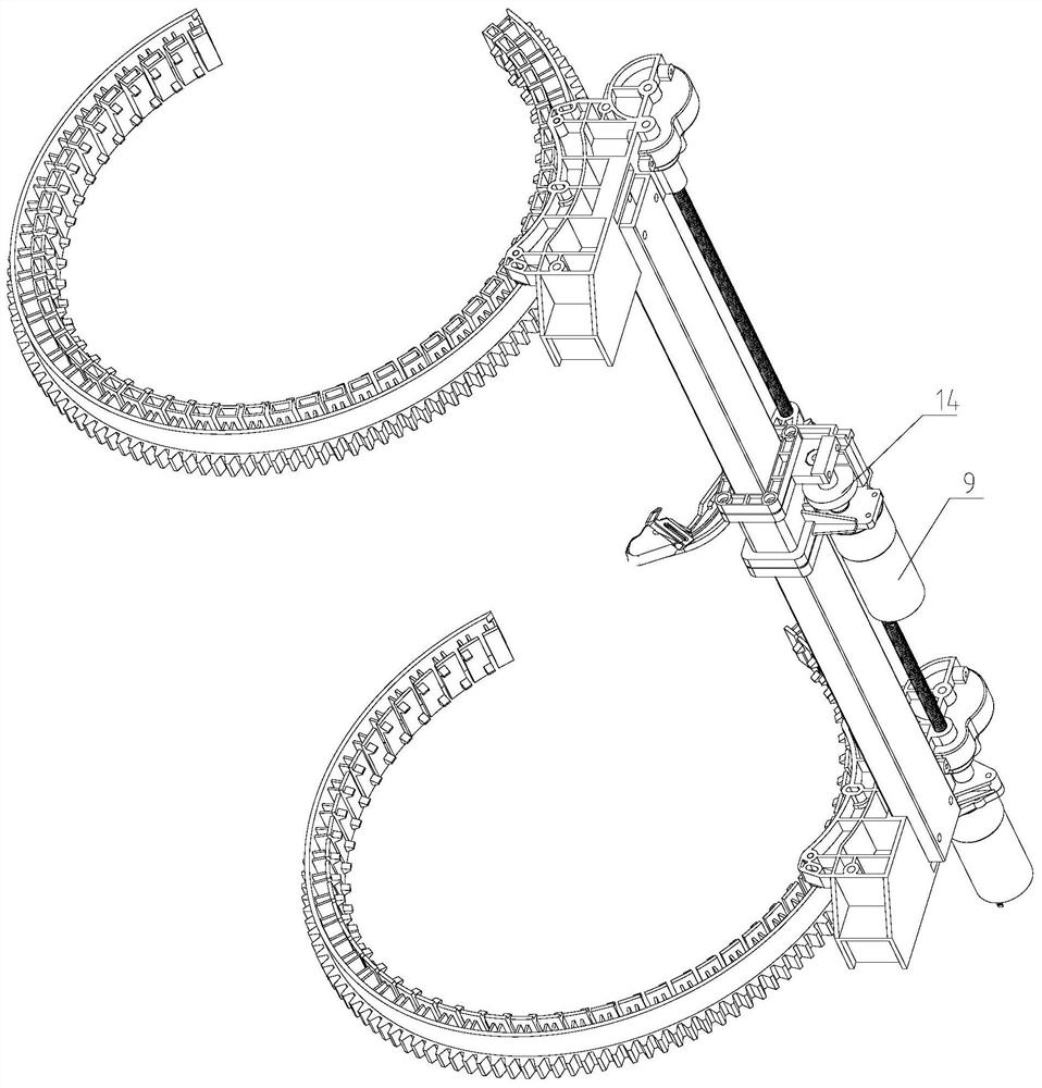
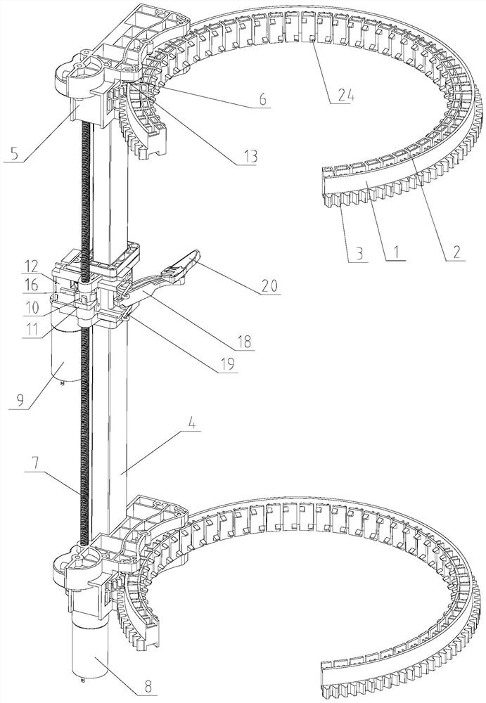
[0040] Example 1, such as figure 1, as shown in 2, this embodiment discloses a rubber tapping machine, the rubber tapping machine includes two deformable guide rails 1 up and down, a chute 2 is formed between the inner and outer walls of the deformable guide rails, and the outer wall of the deformable guide rail 1 is arranged outside Teeth 3; the rubber tapping machine also includes a longitudinal guide rail 4, the upper and lower guide rail frames 5 are respectively installed at the two ends of the longitudinal guide rail 4, inner grooves are arranged on the rail frame 5, and the upper and lower two deformable guide rails 1 are inserted into the upper and lower guide rails respectively In the inner groove of the frame 5, the gears in the guide rail frame 5 are meshed with the teeth 3 on the outer wall of the deformable guide rail, and the horizontal limit wheel 6 and the longitudinal limit slider 13 are respectively arranged on the upper and lower guide rail frames. The posit...


PUM


Abstract

The invention discloses a rubber tapping machine and a rubber tapping method. The rubber tapping machine comprises an upper deformable guide rail and a lower deformable guide rail; a sliding groove isformed between the inner wall and the outer wall of each deformable guide rail, and teeth are arranged on the outer side of the outer wall of each deformable guide rail; the rubber tapping machine further comprises a longitudinal guide rail; an upper guide rail frame and a lower guide rail frame are installed at two ends of the longitudinal guide rail respectively; inner grooves and transverse limiting wheels are arranged on the guide rail frames; gears in the guide rail frames are meshed with the teeth on the outer walls of the deformable guide rails, and the transverse limiting wheels are embedded into the corresponding sliding grooves in the deformable guide rails; in addition, a lead screw is installed between the upper and lower guide rail frames, one end of the lead screw is fixedlyconnected with motor teeth of a motor I, and the other end of the lead screw is fixedly connected with a driving gear; and the rubber tapping machine further comprises a tool rest assembly arranged on the longitudinal guide rail and the lead screw in a sleeving mode. According to the rubber tapping machine disclosed by the invention, the deformable guide rails are used, so that the rubber tappingmachine can be suitable for trunks with different thicknesses and shapes; the whole rubber tapping machine can be firmly fixed on the trunks by cooperation with a tightening belt; and in addition, the deformable guide rails also play a transmission role in a rubber tapping process.

Description

technical field [0001] The invention relates to the field of agricultural machinery, in particular to a rubber tapping machine and a tapping method for cutting rubber tree bark in this field. Background technique [0002] Since humans discovered that natural rubber can be collected from rubber trees, the method of making rubber bark to form rubber slides has always been cutting with a manual hand-held rubber tapping knife; although electric rubber tapping knives have appeared in modern times, manual hand-held operation is still required. [0003] Chinese invention patent application CN104429813A discloses a rubber tapping machine, which includes a tree-tying fixed frame and two ring-shaped planetary gear casings installed on the upper and lower ends of the tree-tying fixed frame respectively, and a vector moving tool rest assembly is set between the two planetary gear casings; The gear shaft is set on the moving knife rest assembly, and the motor and the rubber tapping knife...

Claims


Application Information

Patent Timeline
IPC IPC(8): A01G23/12A01G23/10
CPCA01G23/12A01G23/10
Inventor 许振昆吴纪营张兴明
Owner NINGBO CIHEVEA TECH CO LTD
Why Eureka
Try Eureka