Ultrasonic atomization sheet and ultrasonic atomizer

A technology of ultrasonic atomizing sheet and one side, which is applied in the direction of spraying devices, liquid spraying devices, tobacco, etc., and can solve problems such as weak vibration, low atomization efficiency of ultrasonic atomizing sheets or ultrasonic atomizers, and easy damage

Pending Publication Date: 2020-11-24
钟术光
View PDF8 Cites 3 Cited by
  • Summary
  • Abstract
  • Description
  • Claims
  • Application Information

AI Technical Summary

Problems solved by technology

[0009] 1) Because of the length-width direction non-thickness direction driving mode, this stretching vibration in the length-width direction non-thickness direction makes the atomization efficiency of the ultrasonic atomizing sheet or ultrasonic atomizer very low, and makes the ultrasonic fog The vibration of the center of the chip is too large, the heat is serious, the noise is loud, and it is easy to be damaged;
[0010] 2) Because the piezoelectric substrate is long and has poor mechanical strength and is not shock-resistant, it is easily damaged during vibration work or when it is dropped or hit;
[0011] 3) Because of the need for a certain mechanical strength, the piezoelectric matrix should not be too thin (however, the thinner the piezoelectric matrix, the stronger the vibration and the higher the atomization efficiency), the piezoelectric matrix will

Method used


Image

  • Ultrasonic atomization sheet and ultrasonic atomizer
  • Ultrasonic atomization sheet and ultrasonic atomizer
  • Ultrasonic atomization sheet and ultrasonic atomizer

Examples


specific example

[0096] Other specific examples are: one-component systems such as BaTiO3, PbTiO3, KxWO3, PbNb2O6, etc.; two-component systems such as PbTiO3-PbZrO3, PbTiO3-Pb(Mg1 / 3Nb2 / 3)O3, etc.; -Pb(Mg1 / 3Nb2 / 3)O3, PbTiO3-PbZrO3-Pb(Co1 / 3Nb2 / 3)O3, K1-x-zNaxLizNO3 (such as {LiX(K1-YNaY)1-X}(Nb1-Z-WTaZSbW) O3, etc.) etc. Specific examples of composite oxides and compounds that can be used in the present invention can be found in CN1206700A. Derivatives of the substances shown in Table 1 obtained by partially substituting any of Ba, Sr, Ca, etc. for Pb, or partially substituting Sn, Hf, etc. for Ti, can also be used.

[0097] The above-mentioned piezoelectric ceramic plate material can also be mixed with a polymer material to form a piezoelectric sheet. Examples of the above polymer materials are fluoroplastics (such as polyvinylidene fluoride, polytetrafluoroethylene), polylactic acid, silica gel and the like.

[0098] The piezoelectric ceramic preferably contains 0.1% by mass or less of carb...


PUM


Abstract

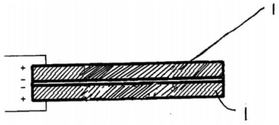
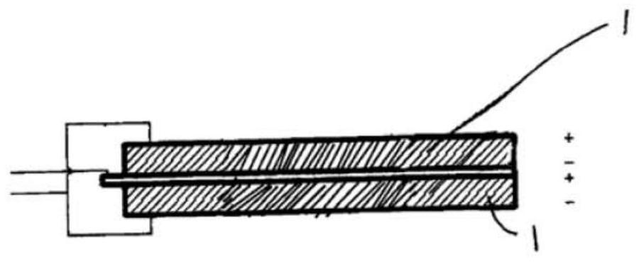
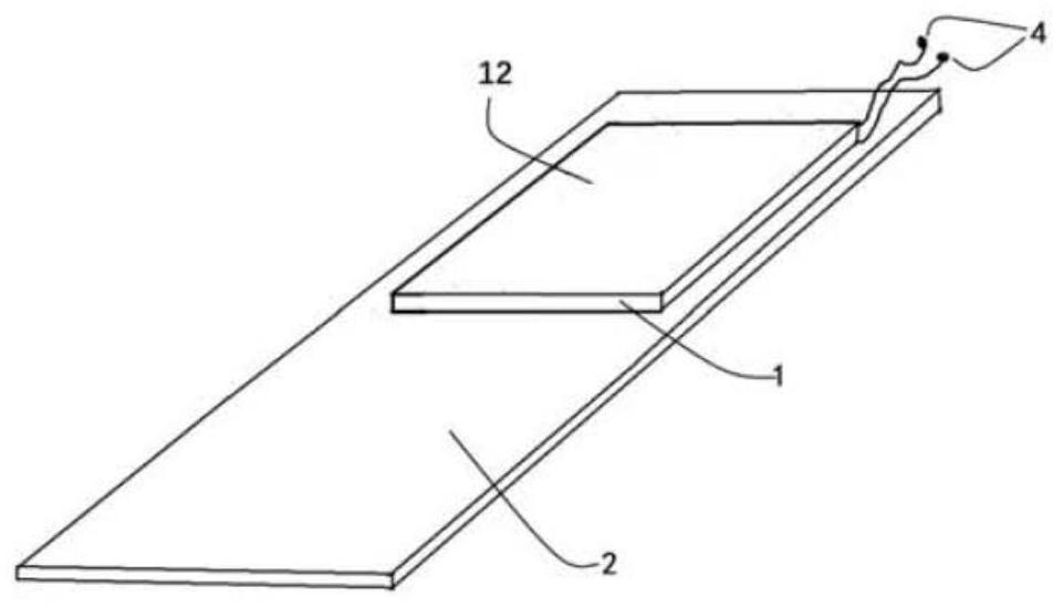
The invention discloses an ultrasonic atomization sheet and an ultrasonic atomizer. The ultrasonic atomization sheet comprises a piezoelectric ceramic plate and a vibration plate, wherein the piezoelectric ceramic plate is arranged on the vibration plate, an overlapping region is arranged between the piezoelectric ceramic plate and the vibration plate as viewed from the thickness direction, the area of the overlapping region accounts for 50% or more of the area of the piezoelectric ceramic plate, opposite electrodes are arranged on the two opposite surfaces of the piezoelectric ceramic plate or/and between the two opposite surfaces of the piezoelectric ceramic plate to form one or more piezoelectric active areas, alternating current is applied between the electrodes to enable the ultrasonic atomization piece to vibrate in the thickness direction of the ultrasonic atomization piece, the piezoelectric ceramic plate and the vibration plate are basically or generally square flat bodies, and the piezoelectric ceramic plate is free of through holes. According to the ultrasonic atomization piece, the occupied space is basically unchanged, the atomization efficiency is remarkably improved,or the occupied space is remarkably reduced due to the basically unchanged atomization efficiency, during atomization, the temperature rise range is reduced, the noise is reduced, the possibility ofdamage is low, and the mechanical strength is improved; and the size is reduced, lightness and thinness are achieved, and carrying is convenient.

Description

【Technical field】 [0001] The invention relates to an ultrasonic atomizing sheet and an ultrasonic atomizer. More specifically, the present invention relates to a multi-purpose ultrasonic atomizing sheet and ultrasonic atomizer with improved performance. [0002] 【technical background】 [0003] Current ultrasonic atomizers or ultrasonic atomizing sheets typically have a structure in which a vibrating sheet is formed by bonding a circular metal plate to one surface of a circular piezoelectric ceramic plate, wherein the piezoelectric ceramic plate The peripheral part is supported in the circular wall of the metal plate, wherein there is a through hole in the center of the piezoelectric ceramic plate, and the center of the metal plate has a number of microporous atomization areas penetrating up and down inside, and the microporous area is opposite to the through hole. However, this ultrasonic nebulizer or ultrasonic atomizing sheet has many disadvantages, such as its small effec...

Claims


Application Information

Patent Timeline
IPC IPC(8): B06B1/06B05B17/06A24F40/40A24F40/10
CPCA24F40/10A24F40/40B05B17/06B05B17/0607B05B17/0653B06B1/0648B06B2201/55B06B2201/77
Inventor 钟术光
Owner 钟术光
Why Eureka
Try Eureka