Pipeline batch bending tool

A batch and pipeline technology, which is applied in the field of pipeline batch bending tools, can solve the problems of low bending speed, difficulty in consistent arc, and difficult control of bending force, so as to improve processing efficiency and reduce processing intensity.

Pending Publication Date: 2020-11-24
SHANDONG ELECTRIC POWER CONSTR NO 2
View PDF0 Cites 0 Cited by
  • Summary
  • Abstract
  • Description
  • Claims
  • Application Information

AI Technical Summary

Problems solved by technology

Industrial instrumentation tubes are mostly Ф10-Ф16 stainless steel and carbon steel small-diameter pipes. Generally, conventional instrumentation pipe benders are powered by manpower, and can only bend one piece at a time, and the bending speed is very l

Method used


Image

  • Pipeline batch bending tool
  • Pipeline batch bending tool
  • Pipeline batch bending tool

Examples


Example Embodiment

[0034] The technical solutions of the present invention will be clearly and completely described below in conjunction with the accompanying drawings. Apparently, the described embodiments are some of the embodiments of the present invention, but not all of them. Based on the embodiments of the present invention, all other embodiments obtained by persons of ordinary skill in the art without making creative efforts belong to the protection scope of the present invention.

[0035] In the description of the present invention, it should be noted that the terms "center", "upper", "lower", "left", "right", "vertical", "horizontal", "inner", "outer" etc. The indicated orientation or positional relationship is based on the orientation or positional relationship shown in the drawings, and is only for the convenience of describing the present invention and simplifying the description, rather than indicating or implying that the referred device or element must have a specific orientation, ...


PUM


Abstract

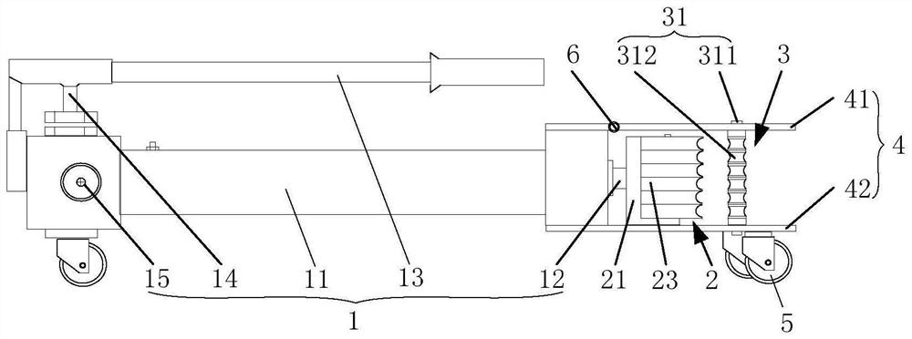
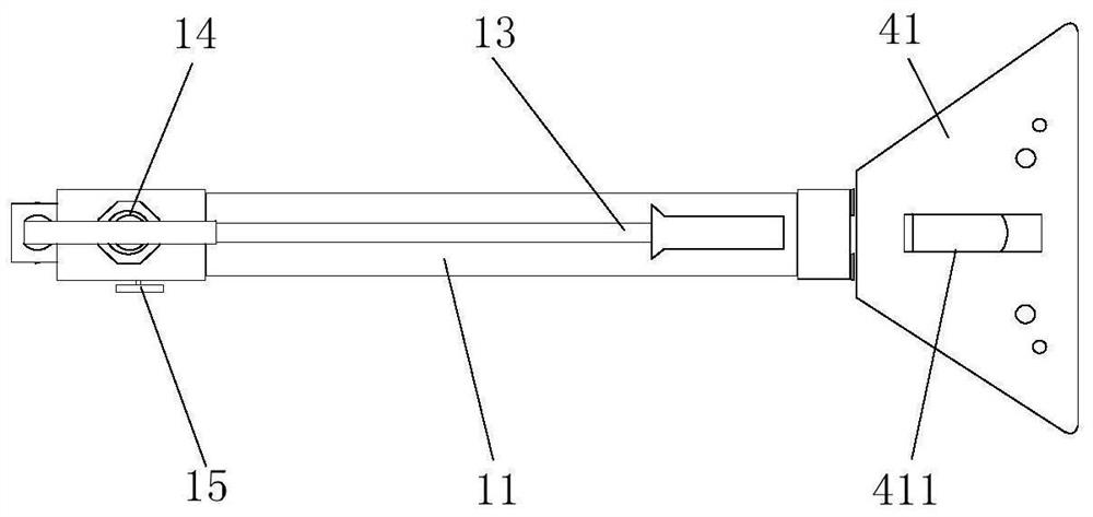
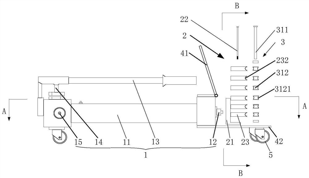
The invention provides a pipeline batch bending tool, and relates to the technical field of pipe bending tools. The pipeline batch bending tool provided by the invention comprises a power mechanism, amoving mechanism and a positioning mechanism. The power mechanism is connected with the moving mechanism. The moving mechanism and the positioning mechanism are oppositely arranged. The power mechanism is provided with a fixed end and a movable end. The movable end of the power mechanism is used for pushing the moving mechanism to get close to the positioning mechanism, so that a channel used forclamping and bending a plurality of pipelines is formed between the moving mechanism and the positioning mechanism. According to the pipeline batch bending tool provided by the invention, the power mechanism replaces pure manual operation; and moreover, the multiple instrument pipelines can be bent at the same time, batch processing of the instrument pipelines is realized, processing intensity isrelieved and processing efficiency is improved.

Description


Claims


Application Information

Patent Timeline
Owner SHANDONG ELECTRIC POWER CONSTR NO 2
Why Eureka
Try Eureka