Laser cutting protection device for support ring

A laser cutting and protection device technology, applied in the direction of laser welding equipment, metal processing equipment, welding equipment, etc., can solve the problems affecting welding operation, damage, etc., and achieve the effect of improving processing efficiency and avoiding blockage

Active Publication Date: 2020-11-24
翊鹏(湖北)实业有限公司
View PDF4 Cites 2 Cited by
  • Summary
  • Abstract
  • Description
  • Claims
  • Application Information

AI Technical Summary

Problems solved by technology

[0002] As shown in the figure, the support ring of the weapon seat is a ring-mounted structure, and the outer ring has a mounting port, which is welded at the bottom of the weapon seat to support the weapon seat. The existing processing method is to cut and install the raw material of the pipe fittings by a CNC laser cutting machine Then the pipe is ring-cut, and the above operation is repeated on the raw material of the pipe to realize the continuous processing of the support ring. However, in the existing processing process, the laser will pass through the pipe wall and generate sparks and flying chips. The raw material of the pipe fittings is damaged, and the flying chips will adhere to the inner wall of the pipe fittings and affect the subsequent welding operation

Method used


Image

  • Laser cutting protection device for support ring
  • Laser cutting protection device for support ring
  • Laser cutting protection device for support ring

Examples


Embodiment Construction

[0036] The technical solutions of the present invention will be clearly and completely described below in conjunction with specific embodiments. Apparently, the described embodiments are only some of the embodiments of the present invention, not all of them. Based on the embodiments of the present invention, all other embodiments obtained by persons of ordinary skill in the art without creative efforts fall within the protection scope of the present invention.

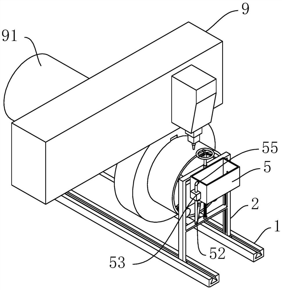
[0037] As shown in the figure, the support ring 8 is a ring-mounted structure, and the outer ring is provided with a mounting opening 81 .

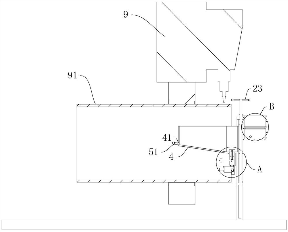
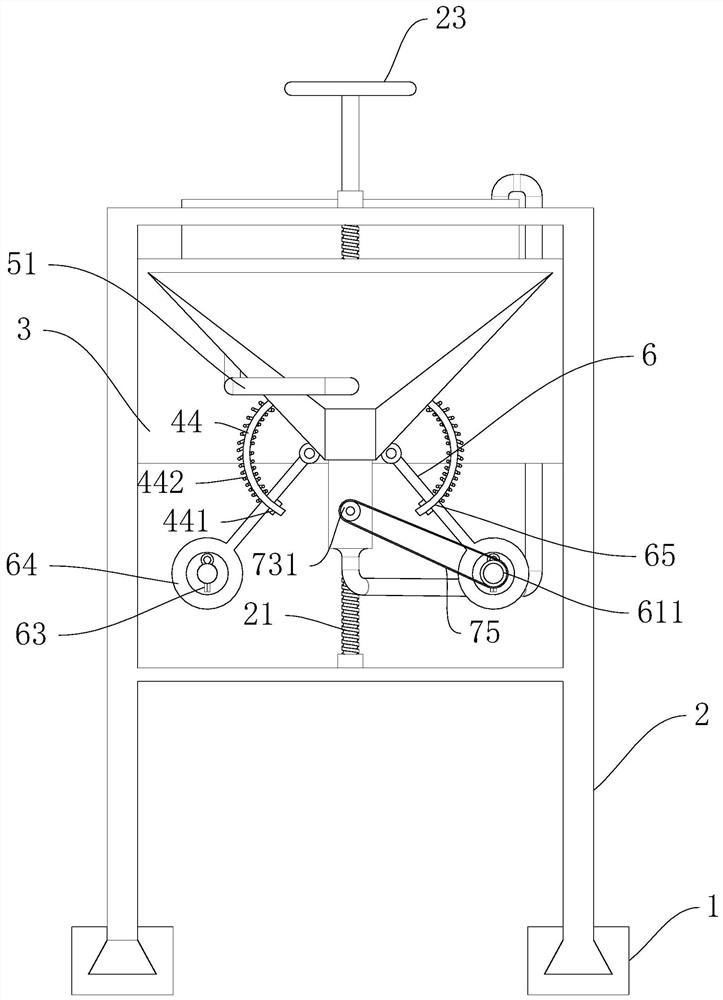
[0038] Example, laser cut protection of support rings, such as figure 1 , figure 2 As shown, it includes an adjustment slide rail 1, an adjustment frame 2 slidably connected to the adjustment slide rail 1, a positioning plate 3 is slidably connected to the adjustment frame 2, and a protection tank 4 inclined on a vertical plane is arranged on the positioning plate 3 to protect ...


PUM


Abstract

The invention relates to the field of laser cutting, and discloses a laser cutting protection device for a support ring. The laser cutting protection device for the support ring comprises an adjustingslide rail and an adjusting frame, wherein a positioning plate is slidably connected onto the adjusting frame; a protection water tank is arranged on the positioning plate; a water inlet and a wateroutlet are respectively formed in the high end and the low end of the protection water tank; and a water storage tank is arranged on the adjusting frame. The laser cutting protection device for the support ring provided by the invention has the following advantages and effects that the protection water tank located under a laser cutter bit is arranged in a pipe fitting, and a water flow in the protection water tank resists and cools splashed molten slag sparks, so that the lower part of the pipe fitting is protected; secondly, adhered waste materials are pressed and broken through a pressing roller group so as to be separated from a support ring in the cutting process, so that the processing efficiency is improved; and then, a stirring paddle rotating along with a pressing shaft is rotatably connected into the water outlet, and the stirring paddle rotates to stir molten slags when the pipe fitting is rotatably cut, so that the blockage of the molten slags on a water outlet pipeline isavoided.

Description

technical field [0001] The invention relates to the technical field of laser cutting, in particular to a laser cutting protection device for a support ring. Background technique [0002] As shown in the figure, the support ring of the weapon seat is a ring-mounted structure, and the outer ring has a mounting port, which is welded at the bottom of the weapon seat to support the weapon seat. The existing processing method is to cut and install the raw material of the pipe fittings by a CNC laser cutting machine Then the pipe is ring-cut, and the above operation is repeated on the raw material of the pipe to realize the continuous processing of the support ring. However, in the existing processing process, the laser will pass through the pipe wall and generate sparks and flying chips. The raw material of the pipe fittings is damaged, and the flying debris will adhere to the inner wall of the pipe fittings and affect the subsequent welding operation. Contents of the invention ...

Claims


Application Information

Patent Timeline
Patent Type & Authority Applications(China)
IPC IPC(8): B23K26/38B23K26/70
CPCB23K26/38B23K26/702B23K26/703Y02P70/10
Inventor 易鹏宋士宁
Owner 翊鹏(湖北)实业有限公司
Why Eureka
Try Eureka