
Optical glass rod grooving machine

A technology of optical glass and slotting machine, which is applied in the direction of working accessories, stone processing tools, stone processing equipment, etc., and can solve the problems of inability to process optical glass rods and the inability to flexibly adjust the position of the drill bit, etc.

Inactive Publication Date: 2020-11-24
湖北光锐鑫光电科技有限公司
View PDF14 Cites 0 Cited by
  • Summary
  • Abstract
  • Description
  • Claims
  • Application Information

AI Technical Summary

Problems solved by technology

[0004] The purpose of the present invention is to solve the disadvantages in the prior art that the position of the drill bit of an optical glass rod slotting machine cannot be adjusted flexibly, so that optical glass rods of different specifications cannot be processed, and a kind of optical glass rod is proposed Slotting machine

Method used


Image

  • Optical glass rod grooving machine
  • Optical glass rod grooving machine
  • Optical glass rod grooving machine

Examples


Embodiment 1

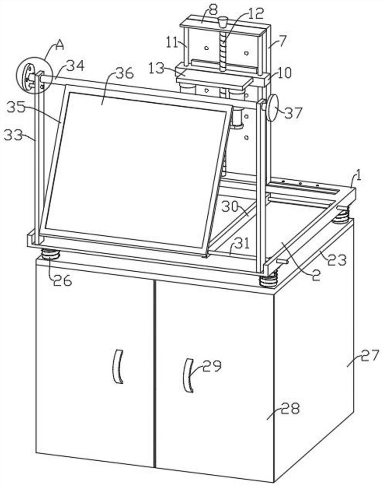
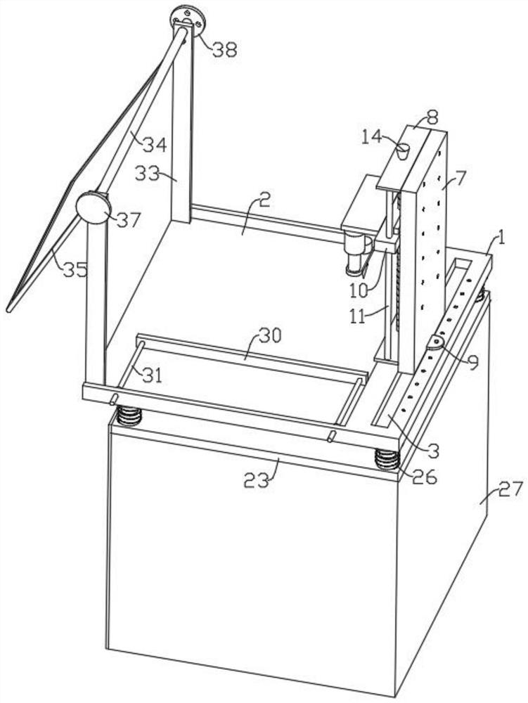
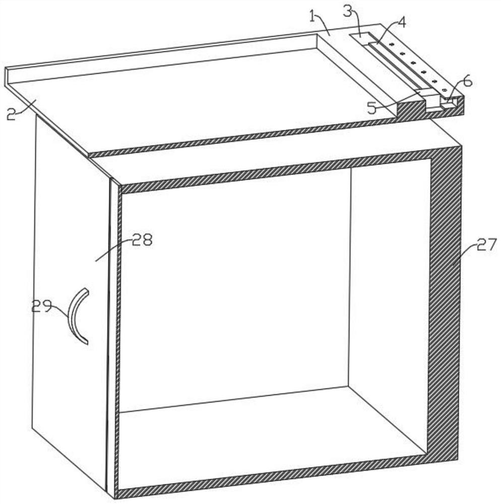
[0023] refer to Figure 1-5 , an optical glass bar stock slotting machine, comprising a base plate 1, a workpiece groove 2 is provided on the top of the base plate 1, a chute 3 is provided on one side of the top of the base plate 1, a card slot 4 is provided on one side of the chute 3, and a chute 3 A slider 5 is provided for sliding inside, and a block 6 is fixedly installed on one side of the slider 5, and the block 6 is slidably arranged in the slot 4, and a vertical beam 7 is fixedly installed on the top of the slider 5, and the lower end of one side of the vertical beam 7 is fixedly installed There is a connecting piece 9, and a plurality of threaded holes are provided on the base plate 1, and the connecting piece 9 is connected with the base plate 1 through screws, and horizontal plates 8 are fixedly installed at the upper and lower ends of one side of the vertical beam 7, respectively. The movable seat 10 is provided with guide rods 11 between the two horizontal plates ...

Embodiment 2

[0026] refer to Figure 1-5 , as another preferred embodiment of the present invention, the difference from Embodiment 1 is that a backing plate 23 is provided at the bottom of the bottom plate 1, and a shock absorbing mechanism is provided at the four corners of the top of the backing plate 23, and the shock absorbing mechanism includes a sleeve 24 , the sleeve 24 is fixedly installed on the top of the backing plate 23, the inner column 25 is inserted in the sleeve 24, the sleeve 24 and the inner column 25 are covered with a spring 26, and the upper and lower ends of the spring 26 are respectively fixed to the bottom plate 1 and the backing plate 23 To connect, by setting a shock-absorbing mechanism, the shock-absorbing property of the spring 26 is used to slow down the vibration generated when the motor 20 is working, so that the slotting drill bit 19 is not easy to vibrate when it is working, and the precision of slotting is improved.

[0027] Backing plate 23 bottoms recei...


PUM


Abstract

The invention relates to the technical field of grooving machines, in particular to an optical glass rod grooving machine. The optical glass rod grooving machine comprises a base plate. The top of thebase plate is provided with a workpiece groove. One side of the top of the base plate is provided with a sliding groove. One side of the interior of the sliding groove is provided with a clamping groove. A sliding block is slidably arranged in the sliding groove. A clamping block is fixedly mounted on one side of the sliding block. The clamping block is slidably arranged in the clamping groove. Avertical beam is fixedly mounted on the top of the sliding block. The lower end of one side of the vertical beam is fixedly provided with a connecting sheet. The base plate is provided with a plurality of threaded holes. Hydraulic cylinders are fixedly mounted at the bottoms of cylinder bases. A carrying plate is arranged at the bottom end of a supporting plate. The bottom end of a rod is fixedlyprovided with a grooving drill bit. A motor is fixedly mounted on the top of the carrying plate. The vertical beam can be moved along the sliding groove, and the connecting sheet is connected to thebase plate, so that the position of the grooving drill bit is adjusted in the horizontal direction. A movable seat can move up and down along guide rods by rotating a rotary handle, so that the heightof the drill bit is arranged in the vertical direction. The optical glass rod grooving machine is suitable for grooving of different sizes of materials and different portions of the materials.

Description

technical field [0001] The invention relates to the technical field of slotting machines, in particular to an optical glass rod slotting machine. Background technique [0002] Optical glass rods can change the direction of light propagation and change the relative spectral distribution of ultraviolet, visible or infrared light. Optical glass in the narrow sense refers to colorless optical glass; optical glass in the broad sense also includes colored optical glass, laser glass, quartz optical glass, anti-radiation glass, ultraviolet and infrared optical glass, fiber optic glass, acousto-optic glass, magneto-optical glass and photochromic Glass. Optical glass can be used to manufacture lenses, prisms, mirrors and windows in optical instruments. Components made of optical glass are key elements in optical instruments. [0003] There is an existing slotting machine for slotting plate-shaped optical glass rods. The motor drives the slotting drill to rotate and cooperates with ...

Claims


Application Information

Patent Timeline
Patent Type & Authority Applications(China)
IPC IPC(8): B28D1/00B28D7/04B28D7/00
CPCB28D1/00B28D7/04B28D7/00
Inventor 田静董小强李涛
Owner 湖北光锐鑫光电科技有限公司
Learn More