Automatic cloth cutting equipment for garment production
A cloth and automatic technology, applied in the cutting of textile materials, textiles and papermaking, etc., can solve a large number of manual operations, hidden dangers, and safety problems, and achieve the effect of simple and safe operation and reduced labor load
- Summary
- Abstract
- Description
- Claims
- Application Information
AI Technical Summary
Problems solved by technology
Method used
Image

Examples
Embodiment 1
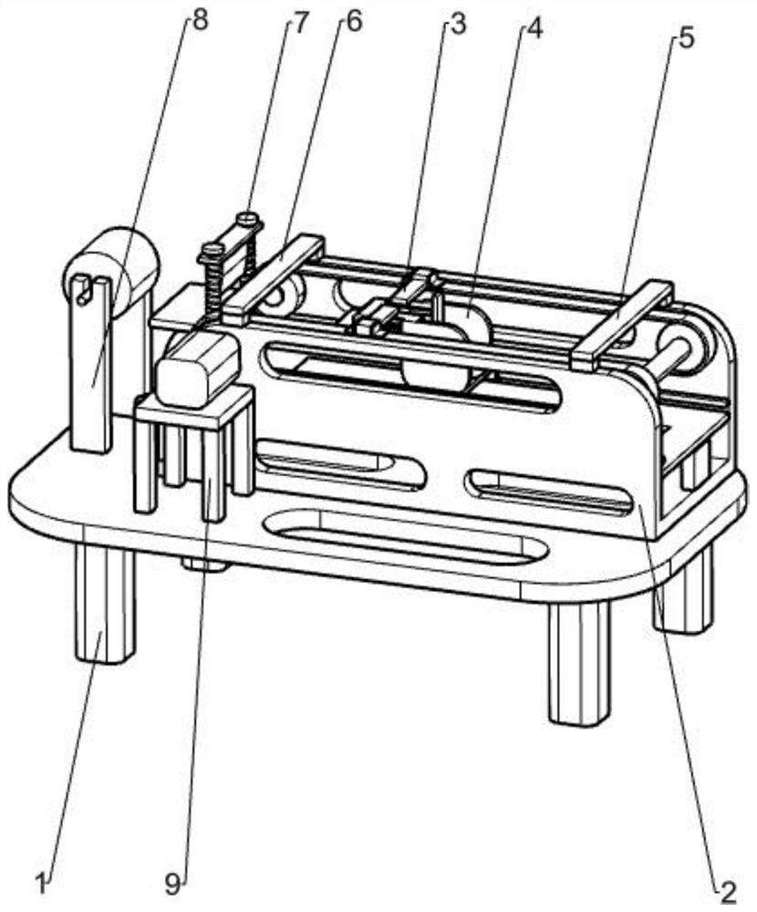
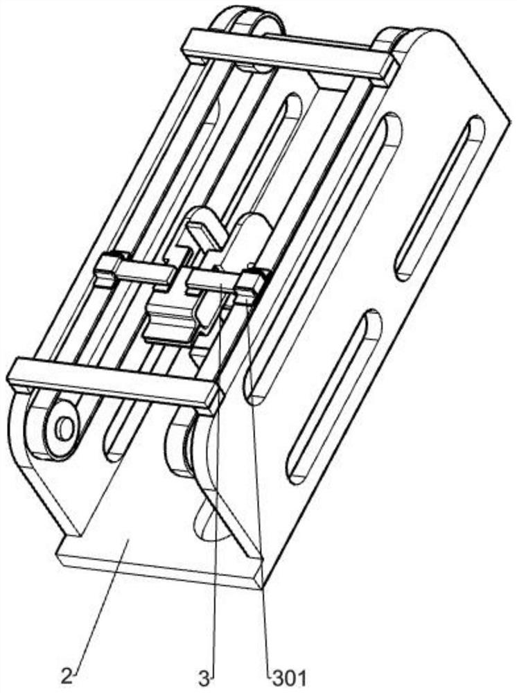
[0084] A cloth automatic cutting device for garment production, such as Figure 1-14 As shown, it includes a support one 1, a support two 2, a linear guide rail 202, a cloth placing plate 201, a jaw cloth taking mechanism and a cloth shearing mechanism, the support two 2 is fixed above the support one 1, and there are two linear guide rails 202, The linear guide rail 202 is symmetrically fixed on both sides of the bracket 2, the cloth release plate 201 is fixed on both sides of the bracket 2 2, the cloth release plate 201 is located below the linear guide rail 202, and the gripping claw cloth taking mechanism is slidably connected to the linear guide rail 202. The cloth cutting mechanism is rotatably connected to the support one 1, and the gripping jaws take the cloth mechanism and connect with the cloth cutting mechanism.
[0085] When cutting the roll of cloth 802, first manually put one end of the roll of cloth 802 under the cloth cutting mechanism, start the gripper to tak...
Embodiment 2
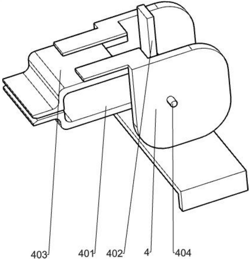
[0087] On the basis of Example 1, such as Figure 2-14 As shown, the gripping claw cloth fetching mechanism includes a support plate 9, a motor base 901, a servo motor 902, a third pulley 903, a third rotating shaft 906, a fourth pulley 904, a flat belt two 905, a connecting plate one 3, a fixed Block 301, bracket three 4, first rotating shaft 404, lower rotating jaw 401, control board 402, upper fixed jaw 403, slider 411, sliding support plate 409, follower block 410, fixed plate one 13, guide rod two 14. Fixed plate 2 15, linear bearing sliding block 16, spring 2 17 and fixed plate 3 18, four support plates 9 are fixed on the top of support 1 1, support plate 9 is located on the front side of support 2 2, motor base 901 is fixed on the support Above the plate 9, the servo motor 902 is installed on the motor base 901, and there are two third pulleys 903, one of which is fixedly connected to the output shaft of the servo motor 902, and the other third pulley 903 rotates to con...
Embodiment 3
[0092] On the basis of Example 2, such as Figure 4-9 As shown, the clamping control mechanism is also included, and the clamping control mechanism includes connecting plate two 408, guide rod one 406, sliding swash plate 405, spring one 407, unclamping baffle 5 and clamping baffle 6, connecting plate The second 408 is fixedly connected to the bracket three 4 and the sliding support plate 409, the first guide rod 406 is two, the first guide rod 406 is symmetrically fixed on the top of the second connecting plate 408, and the two sides of the sliding swash plate 405 are slidably connected to the first guide rod. The slant plate 405 is in contact with the control plate 402, and there are two springs 407. The spring 1 407 is sleeved on the guide rod 1 406. One end of the spring 1 407 is fixedly connected to the sliding swash plate 405, and the other end of the spring 1 407 is fixedly connected to the connecting plate 2. 408, the loosening baffle 5 is fixedly connected to the righ...
PUM
 Abstract
Description
Claims
Application Information
 - R&D Engineer
- R&D Manager
- IP Professional
- Industry Leading Data Capabilities
- Powerful AI technology
- Patent DNA Extraction
Browse by: Latest US Patents, China's latest patents, Technical Efficacy Thesaurus, Application Domain, Technology Topic.
© 2024 PatSnap. All rights reserved.Legal|Privacy policy|Modern Slavery Act Transparency Statement|Sitemap