Oil containment boom facility with crude oil recovery function

An oil boom and functional technology, which is applied in general water supply conservation, cleaning of open water surfaces, water conservancy projects, etc., can solve the problems of poor crude oil recovery effect, no crude oil recovery function, inconvenient use and adjustment, etc., to achieve good oil protection effect, reliable connection, good buoyancy effect

Inactive Publication Date: 2020-11-24
郭雅心
View PDF8 Cites 0 Cited by
  • Summary
  • Abstract
  • Description
  • Claims
  • Application Information

AI Technical Summary

Problems solved by technology

[0003] The existing oil boom facilities have good structural stability, are inconvenient to use and adjust, and do not have the function of crude oil recovery or the crude oil recovery effect is poor, so there are limitations

Method used


Image

  • Oil containment boom facility with crude oil recovery function
  • Oil containment boom facility with crude oil recovery function
  • Oil containment boom facility with crude oil recovery function

Examples


Embodiment 1

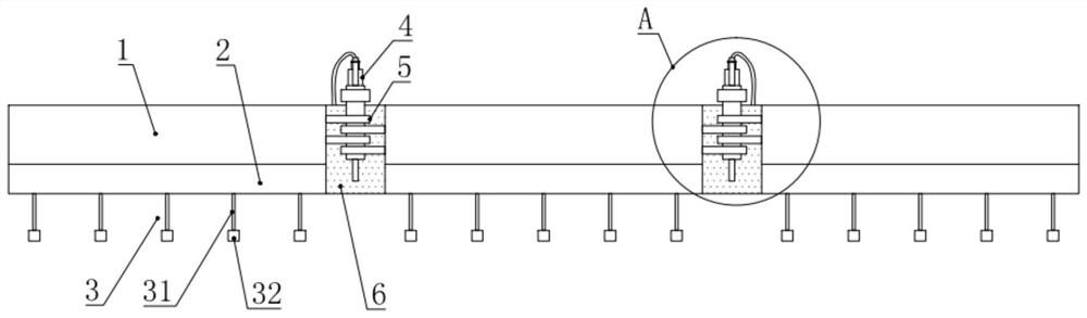
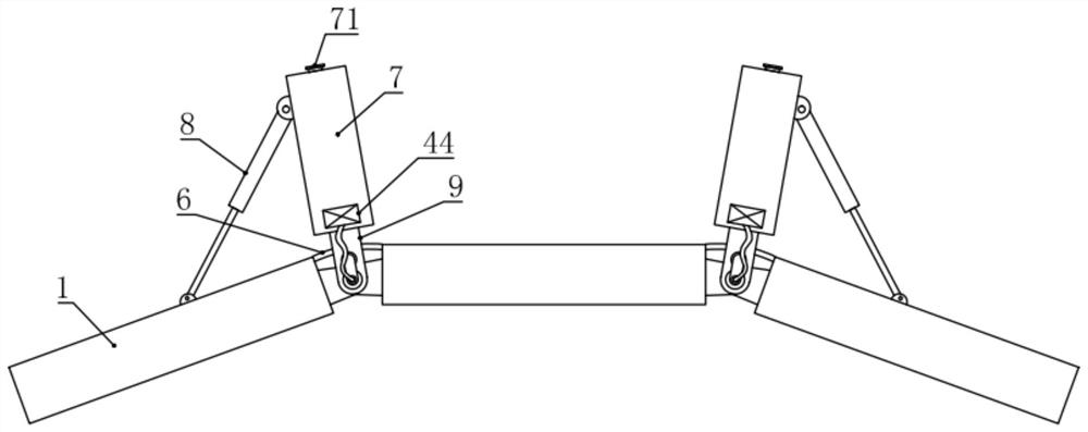
[0031] see figure 1 and 3 , in the embodiment of the present invention, an oil containment boom facility with crude oil recovery function includes three buoys 1, the three buoys 1 are sequentially connected by a hinge assembly 5, and there is a gap between two adjacent buoys 1 An elastic plate 6 is connected, and the oil retaining effect is played through the elastic plate 6. The rear side between two adjacent buoys 1 is also provided with an oil storage buoy 7, and the oil storage buoy 7 is also passed through a fixed plate 9 Connected and fixed with the hinge assembly 5, the oil storage buoy 7 is also equipped with an oil pumping device 4 for extracting crude oil between two adjacent buoys 1, and the rear sides of the two buoys 1 at both ends are A second telescopic cylinder 8 is also hinged, and the other end of the second telescopic cylinder 8 is hinged on the side of the oil storage buoy 7, and the two buoys 1 at both ends can be driven to rotate by the second telescopic...

Embodiment 2

[0036] see Figure 1-7 , the difference between this embodiment and embodiment 1 is:

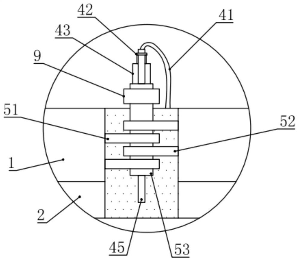
[0037] In this example, if figure 2 As shown, the hinge assembly 5 includes a first hinge plate 51, a second hinge plate 52 and a hinge tube 53, the hinge tube 53 is vertically arranged, and the hinge tube 53 is rotatably connected with two first hinge plates 51 and two hinge tubes. Two second hinged plates 52, and two first hinged plates 51 and two second hinged plates 52 are vertically evenly staggered, and the two first hinged plates 51 are fixed on the buoy 1 on one side of the hinged pipe 53, two The second hinged plate 52 is fixed on the buoy 1 on the other side of the hinged pipe 53; the fixed plate 9 is fixed on the front end of the oil storage float 7, and the fixed plate 9 is fixed to the hinged pipe 53 of the hinged assembly 5 connect.

[0038] In this example, if Figure 4 and 5 As shown, the buoy 1 is a closed cylindrical shell structure, and the inner side of the buoy 1 i...


PUM


Abstract

The invention relates to the technical field of environmental protection, in particular to an oil containment boom facility with a crude oil recovery function. The oil containment boom facility with the crude oil recovery function comprises three buoys, the three buoys are sequentially connected through hinge assemblies, an elastic plate is further connected between two adjacent buoys, an oil storage buoy is further arranged on the rear side between two adjacent buoys, the oil storage buoys are further fixedly connected with the hinge assemblies through fixing plates, oil pumping devices usedfor pumping crude oil between every two adjacent buoys are further installed on the oil storage buoys, second telescopic cylinders are further hinged to the rear sides of the two buoys at the two ends, the other ends of the second telescopic cylinders are hinged to the side faces of the oil storage buoys, oil baffles are further installed on the lower sides of the buoys, and a plurality of counterweight assemblies are installed on the lower sides of the oil baffles. The oil containment boom facility is good in stability, convenient to use and adjust, better in crude oil recovery function and beneficial to application and popularization.

Description

technical field [0001] The invention relates to the technical field of environmental protection, in particular to an oil boom facility with crude oil recovery function. Background technique [0002] With the development of marine transportation, offshore oil industry, and crude oil submarine transportation, oil spill pollution accidents in water areas occur from time to time; once an oil spill accident occurs, if it is not dealt with in a timely and effective manner, it will have a negative impact on the economic activities and ecology of the accident area. The system delivers a fatal blow. In the process of oil spill treatment, the oil boom must be deployed in a timely and effective manner to contain and concentrate the spilled oil, and then recover and treat the spilled oil through various physical, chemical and even biological methods. [0003] The existing oil boom facilities have good structural stability, are inconvenient to use and adjust, and do not have the crude o...

Claims


Application Information

Patent Timeline
IPC IPC(8): E02B15/04E02B15/08E02B15/10
CPCE02B15/04E02B15/08E02B15/0857E02B15/10Y02A20/204
Inventor 郭雅心
Owner 郭雅心
Why Eureka
Try Eureka