Wave energy conversion device and conversion method

A conversion device and wave energy technology, applied in hydropower, engine components, machines/engines, etc., can solve the problems of low energy conversion rate of hard and brittle, expensive materials, poor tensile strength, etc., and achieve strong environmental adaptability, High energy conversion efficiency and avoid strong impact

Active Publication Date: 2020-11-24
HANGZHOU DIANZI UNIV
View PDF11 Cites 4 Cited by
  • Summary
  • Abstract
  • Description
  • Claims
  • Application Information

AI Technical Summary

Problems solved by technology

Magnetostrictive materials mostly use piezoelectric materials, Terfenol-D, etc., but the materials are expensive and have poor tensile strength, while ordinary piezoelectric materials are hard and brittle or have low energy conversion rates

Method used


Image

  • Wave energy conversion device and conversion method
  • Wave energy conversion device and conversion method
  • Wave energy conversion device and conversion method

Examples


Embodiment 1

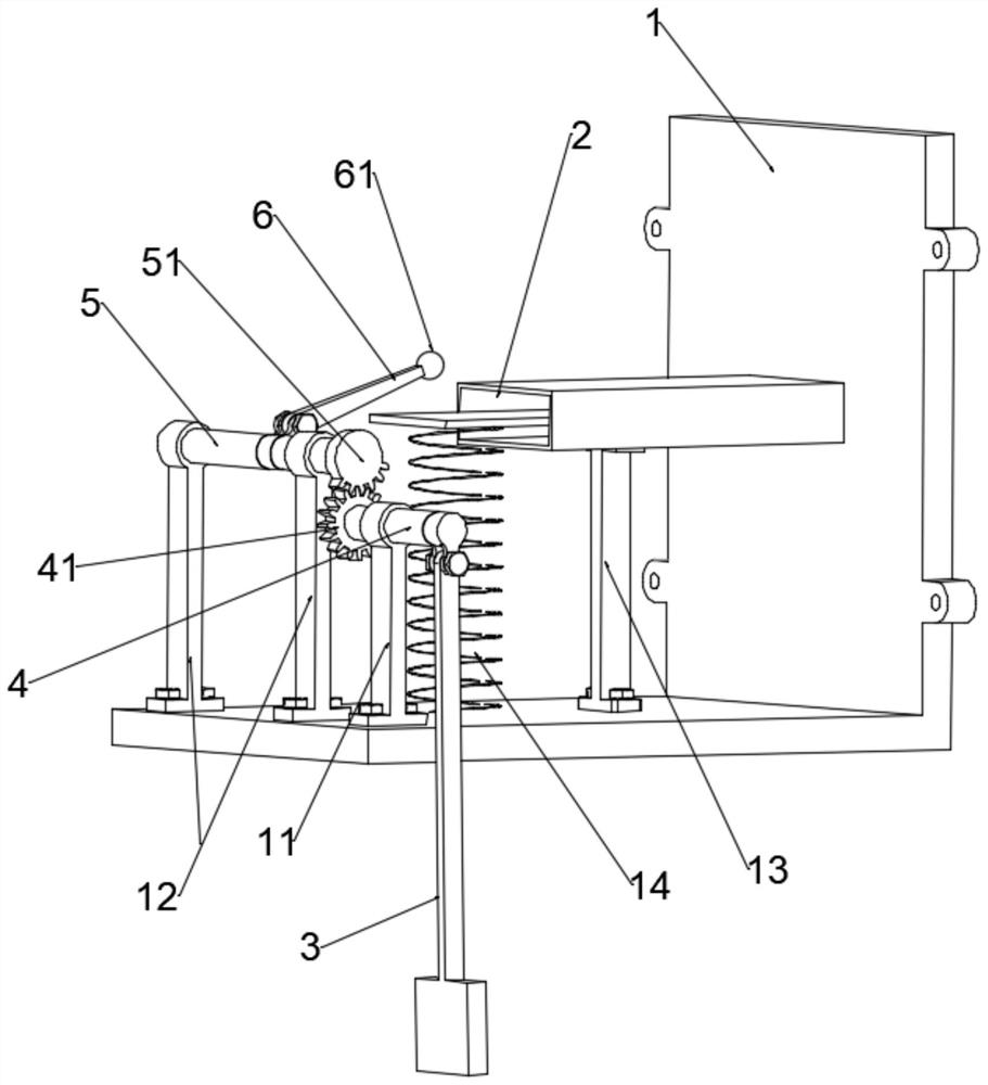
[0036] Such as Figure 1 to Figure 3 As shown, this embodiment provides a wave energy conversion device, including a transmission pendulum 3 , a fixing base 1 , and a transmission mechanism and an energy collection mechanism 2 fixedly installed on the fixing base 1 .

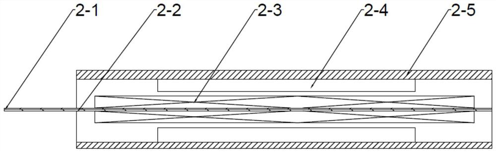
[0037] The energy harvesting mechanism 2 comprises a magnetostrictive sheet, an induction coil 2-3, a permanent magnet 2-4 and a magnetically conductive shell 2-5, wherein the magnetostrictive sheet is a Galfenol sheet 2-1, and the bottom bread of the Galfenol sheet 2-1 Covered with a beryllium bronze sheet 2-2, one end of the magnetostrictive sheet is fixed on the side wall of the fixed base 1, and the other end protrudes outside the magnetically conductive shell 2-5 to form a cantilever beam. The Galfenol sheet 2-1 and the beryllium bronze sheet 2-2 are bonded and connected by epoxy resin, so that the cantilever beam of the magnetostrictive sheet can bear a large bending range. The induction coil 2-3 is wound...

Embodiment 2

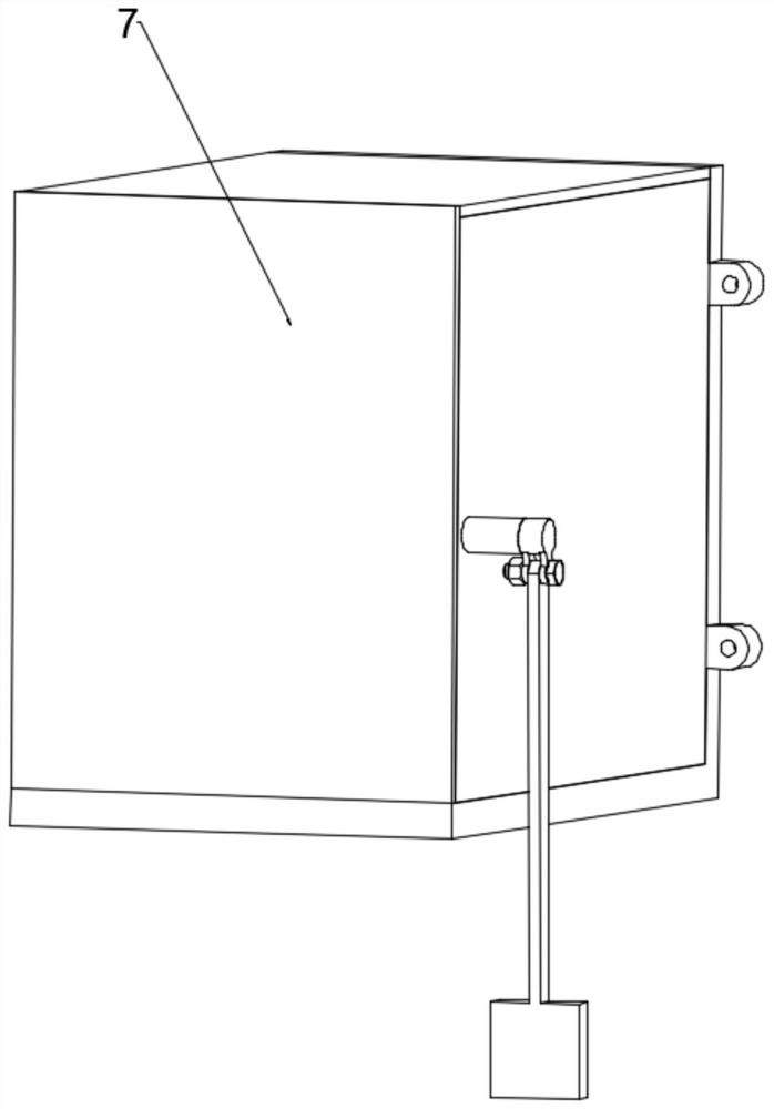
[0055] A wave energy conversion device provided in this embodiment is different from Embodiment 1 in that:

[0056] Such as Figure 4 As shown, the side wall of the fixed seat in this embodiment is fixedly connected to the support 8 . The wave energy conversion structure and the support are connected and fixed by bolts and nuts, and then placed at an appropriate water depth on the shore. This kind of energy conversion and collection is convenient for water basins without embankments, and it is easy to install and has a wide range of applications. For river basins with embankments, the wave energy conversion device is connected and fixed with the expansion bolt installed on the embankment through screw holes through nuts, and the installation height can be determined according to the actual environmental conditions of the river.

[0057] For other specific structures and implementation steps, please refer to Embodiment 1.


PUM


Abstract

The invention belongs to the technical field of wave vibration power generation devices, and particularly relates to a wave energy conversion device. The wave energy conversion device comprises a transmission swing rod, a fixed seat, a transmission mechanism and an energy collection mechanism, wherein the transmission mechanism and the energy collection mechanism are mounted on the fixed seat; theenergy collection mechanism comprises a magnetostrictive sheet, an induction coil, permanent magnets and a magnetic conductive shell, the induction coil is wound on the magnetostrictive sheet, and the permanent magnets are arranged on both sides of the induction coil and are fixed in the magnetic conductive shell; and the transmission mechanism comprises a transmission shaft, an excitation shaftand an excitation swing rod, the excitation swing rod is fixed on the excitation shaft, a transmission swing rod is fixed on the transmission shaft, and the transmission shaft is rotationally matchedwith the excitation shaft through gears. When waves drive the transmission swing rod to swing, the transmission swing rod drives the transmission shaft to move, the excitation shaft rotates in linkageto cause the excitation swing rod to press the magnetostrictive sheet, the magnetostrictive sheet is caused to generate strain, under the action of the magnetic field, stress changes causes changes in magnetic induction intensity, and the induction coil generates an electric potential to realize energy conversion.

Description

technical field [0001] The invention belongs to the technical field of wave vibration power generation devices, and in particular relates to a wave energy conversion device and a conversion method. Background technique [0002] In today's world, as non-renewable traditional energy such as fossil energy is continuously exploited and utilized, energy is becoming more and more scarce. Therefore, the development of new energy has become extremely important. The environment, weather and geographical and many other restrictions. As a green and renewable energy widely existing in oceans, rivers and river basins, wave energy has large reserves, wide distribution, and is not limited by natural conditions. In oceans, rivers, and river basins, not only natural wind blowing will generate waves, but also passing passenger ships, cargo ships, ferries, etc. will also cause waves, which will increase the frequency of wave generation. Therefore, wave energy is a kind of energy with great po...

Claims


Application Information

Patent Timeline
IPC IPC(8): F03B13/00F03B11/00
CPCF03B13/00F03B11/00Y02E10/20
Inventor 孟爱华吴帅兵严纯
Owner HANGZHOU DIANZI UNIV
Why Eureka
Try Eureka